Development version
This book follows the main branch and can describe features that are not in a release yet. The book for the latest release, v0.1.2, is here.
Introduction
Volt is a command-line tool: it has no window of its own. You write your
designs in a text editor and run volt commands in a terminal (PowerShell
on Windows, Terminal on macOS and Linux). Setup shows how,
step by step, if you have never used a terminal.
Volt is also the name of the language those designs are written in, a hardware description language. You describe digital circuits in a Rust-like syntax, and the compiler writes readable SystemVerilog for your FPGA or ASIC tools. Clock domains are part of the type system: a signal that crosses from one clock domain to another without a synchronizer is a compile error.
This book teaches Volt by building things. Setup gets your computer ready: a terminal, a folder, an editor, Volt and Docker Desktop. Then come three parts:
- Part I, the Tour, takes about 15 minutes. You create a project, meet a clock domain crossing error, fix it, run tests and look at a waveform.
- Part II, the Tutorial, builds one design per chapter: a counter, a state machine, a UART, a design with two clocks, and more.
- Part III, the Cookbook, is a set of recipes for common hardware tasks: FIFOs, crossings, reset synchronizers, register maps, pipelines.
Status. Volt is an early-stage project (version 0.1). The Tour and the counter chapter are written; the other chapters list what they will cover and point to working examples in the repository.
Two kinds of readers
This book is written for two groups at once:
- people who are new to hardware and have written software before, and
- FPGA and ASIC engineers who know SystemVerilog.
The main text is for both. It explains what to type and what happens. Two kinds of side boxes add detail for one group. You can skip either kind; the main text reads the same without them.
New to hardware?
Boxes like this one explain a hardware idea the main text uses: a clock, a flip-flop, a reset. If you have designed digital logic before, skip them.
Coming from SystemVerilog?
Boxes like this one show the SystemVerilog you would write for the same thing, what Volt does differently, and why. If SystemVerilog is new to you, skip them.
Code in this book
Every Volt example in this book is checked by volt check in continuous
integration, and the tests in it run in Verilator. Some examples are
wrong on purpose, to show an error; the text says so each time. Command
output is copied from real runs; the chapter says where it ran.
Setup and the Tour label every block: Type this is a command to copy, You should see is what it prints, and Create this file gives a file’s name and contents. Setup explains the three.
The source of this book is in the
book/ directory of the
Volt repository. Corrections are welcome.
Setup
In this chapter you will open a terminal, make a folder for your Volt projects, pick an editor and learn three ways to create a file. Then you will install Volt and Docker Desktop and check that both work. If you use a terminal every day, skim the headings and do the last three sections.
Before you start
- Window: none yet; this page shows how to open a terminal.
- Folder: none yet; this page makes one.
- Running: a web browser with this book, and an internet connection.
Volt is a command-line tool
Volt has no window of its own. You use it in two programs side by side:
- a text editor, where you write designs: files whose names end in
.volt; - a terminal, where you type commands such as
volt checkandvolt test. Volt reads your files, prints what it found, and writes its results into a folder namedbuild.
Open a terminal
A terminal is a window where you type a command and press Enter, and the command prints its answer below it.
- Windows: open the Start menu, type
PowerShelland press Enter. A window opens with a line likePS C:\Users\you>. Windows 11 may show it inside the Terminal app; that is the same thing. Use PowerShell, not Command Prompt: the Windows commands in this book are PowerShell commands. - macOS: press Cmd+Space, type
Terminaland press Enter. - Linux: press Ctrl+Alt+T, or search for Terminal in your applications.
The text before the cursor (PS C:\Users\you> on Windows, something
ending in % or $ on macOS and Linux) is the prompt. It is not part
of any command, and the commands in this book never include it.
The three kinds of blocks in this book
The guided pages (this one and the Tour) label every block:
Type this: a command. Copy it with the button in the block’s top right corner, paste it into the terminal (Windows: right-click or Ctrl+V; macOS: Cmd+V; Linux: Ctrl+Shift+V) and press Enter. Or type it.
volt --version
You should see: what the command prints. These blocks have no copy
button: you compare them with your terminal, you do not type them. Small
differences, such as times like 0.01s, do not matter.
volt 0.1.2 (33354c5)
Create this file: name.volt, followed by the file’s contents. The
section Create a file below shows how.
When Windows and macOS or Linux need different commands, the book shows both, each with its own label: Type this (Windows, PowerShell): and Type this (macOS and Linux):, for example. Use the one for your computer.
Make a folder for your projects
A terminal always works in a folder, its working folder. A new
terminal starts in your home folder (on Windows C:\Users\<your name>).
Commands such as volt new create their files in the working folder.
Make a folder named volt-projects in your home folder. You do this once.
Type this:
mkdir ~/volt-projects
~ means your home folder; it works in PowerShell, on macOS and on
Linux. PowerShell answers with a short table that names the new folder;
macOS and Linux print nothing.
Now go into it. cd means change directory:
Type this:
cd ~/volt-projects
On Windows the prompt now ends in volt-projects>. On every system, pwd
prints the working folder. cd .. goes up one folder; cd ~/volt-projects
brings you back here from anywhere. Every Tour page starts with a cd
command like this one, in its Before you start box, so you always know
where you are.
To see the folder in your file manager:
Type this (Windows, PowerShell):
explorer .
Type this (macOS):
open .
Type this (Linux):
xdg-open .
. means the working folder.
Pick an editor
Any editor that saves plain text works.
- Visual Studio Code (VS Code) is free and runs on Windows, macOS and Linux. We suggest it: it shows the folder and the terminal in the same window (menu Terminal → New Terminal). Open your project with File → Open Folder.
- Notepad (Windows) works too. Read the warning about
.txtbelow. - On macOS, TextEdit saves formatted text by default; choose Format → Make Plain Text before you save, or use VS Code.
Create a file
A guided page shows a file like this:
Create this file: hello.volt
// A wire from one port to another.
pub module Hello {
    in  a : bool
    out b : bool

    b = a
}
The file goes into the working folder named in the page’s Before you
start box. There are three ways to create it. Try one now with
hello.volt, in volt-projects.
With the clipboard
Click the copy button of the file’s block. Then, in the terminal:
Type this (Windows, PowerShell):
Get-Clipboard -Raw | Set-Content hello.volt -NoNewline
Type this (macOS):
pbpaste > hello.volt
Type this (Linux):
wl-paste > hello.volt
wl-paste comes with the wl-clipboard package. On an older X11 desktop
use xclip -selection clipboard -o > hello.volt (package xclip).
These commands write the file in the working folder and replace a file of
the same name if there is one. Put the name of the file you are creating
in place of hello.volt.
With VS Code
Open the folder (File → Open Folder), then File → New File, type
the name hello.volt and press Enter. Paste the contents and save with
Ctrl+S (macOS: Cmd+S).
With Notepad
Open Notepad and paste the contents. Choose File → Save as, go to the
folder (volt-projects is in your user folder, C:\Users\<your name>),
and set Save as type to All files (*.*). Type the name
hello.volt and save.
New to files? The .txt trap
With Save as type left at Text Documents (*.txt), Notepad saves
hello.volt.txt. File Explorer hides the .txt part, so the file looks
right, and then Volt cannot find hello.volt. Typing the name in quotes,
"hello.volt", also stops Notepad from adding .txt.
Check that the file is there
ls lists the files of the working folder, with their full names:
Type this:
ls
You should find hello.volt in the list, not hello.volt.txt.
Replace a file
Some pages change a file you made earlier and say Replace this file: followed by the name. Use the clipboard command again (it replaces the file), or in the editor select everything (Ctrl+A, macOS: Cmd+A), paste the new contents and save.
Install Volt
Type this (Windows, PowerShell):
irm https://volt-hdl.github.io/volt/install.ps1 | iex
Type this (macOS and Linux):
curl -fsSL https://volt-hdl.github.io/volt/install.sh | sh
The script prints each step. When it has finished, close the terminal
and open a new one: a terminal that was already open does not know the
new volt command. If you use the Windows Terminal app or VS Code, close
the whole program, not just the tab.
Install Volt explains what the script changes, how to update or remove Volt, and how to build it from source on a system the script does not support.
Check Volt
In the new terminal:
Type this:
volt --version
You should see:
volt 0.1.2 (33354c5)
This book describes Volt 0.1.2. The book at
https://volt-hdl.github.io/volt/ follows the latest release, and the
book at https://volt-hdl.github.io/volt/dev/ follows the development
version. If volt --version prints another version, some output on these
pages may differ from yours. The seven letters and digits in parentheses
name the commit your copy of Volt was built from; they differ from the
ones above, and a copy built without git shows no parentheses.
If you see “The term ‘volt’ is not recognized” (Windows) or “command not found” (macOS, Linux), the terminal was opened before the install finished: close it, and the program around it, and open a new one.
Install and start Docker Desktop
volt check and volt build need nothing but volt. volt test runs
your design in a simulator called Verilator. If Verilator is not
installed, Volt runs it inside Docker, a program that starts small
prepared Linux systems (containers). So for volt test:
- Install Docker Desktop (Windows, macOS) or Docker Engine (Linux).
- Start it. On Windows, open the Start menu and type
Docker Desktop; on macOS, open it from Applications. - Wait until the Docker Desktop window says Engine running in its bottom left corner.
Installed is not enough: Docker Desktop must be running whenever you
run volt test. If you closed it, start it again and wait for Engine
running. Its settings have an option to start it when you sign in.
Ask volt doctor
volt doctor checks what works on your computer.
Type this:
volt doctor
Your own user folder appears where this output says C:\Users\you.
You should see (Windows 11, Docker Desktop running):
volt 0.1.2 (windows-x86_64)

✓ build, check, explain — no external tools needed
✓ test, run — via Docker (verilator/verilator:v5.054: Verilator 5.054, g++ 13.3)
✓ verify — via Docker (hdlc/formal:all: Yosys 0.66, SBY 0.69, boolector 3.2.4, yices 2.7.0, z3 4.15.0)
- timing (optional) — OpenSTA not found; checks generated .sdc files
- driver checks (optional) — C compiler not found (found: rustc 1.95.0); compiles drivers from --emit=c,rust
✓ docker — 29.8.1, daemon running
- project — no Volt.toml (search stopped at the home directory C:\Users\you); single .volt files still work
The lines that matter for the Tour are build, check, explain and test, run: both need a ✓. Lines starting with - are optional tools.
If Docker Desktop is installed but not running, these lines change:
You should see (Docker Desktop installed, not running):
✗ test, run — Verilator, C++ compiler, make not found
    fix (Windows): start Docker Desktop: Volt runs Verilator in a container (DOCKER below), or use WSL
    see: volt explain simulation-setup
✗ verify — sby, Yosys not found; no SMT solver found (boolector, bitwuzla, yices, z3)
    fix (Windows): start Docker Desktop: Volt runs sby in a container (DOCKER below), or use WSL
    see: volt explain verify-setup
! docker — 29.8.1 installed, daemon not running (start Docker Desktop or the docker service)
Start Docker Desktop, wait for Engine running, and run volt doctor
again. While Docker Desktop is still starting, the docker line may say
daemon did not answer within 5 s; wait a little and try again.
Copy what a command printed
When your terminal shows something other than the You should see block, you may want to compare it closely or ask someone for help. Copy the text:
- Windows: select it with the mouse, then press Enter or Ctrl+C. Careful: Ctrl+C with nothing selected stops the running command.
- macOS: select it, then Cmd+C.
- Linux: select it, then Ctrl+Shift+C.
Or run the command again and send everything it prints straight to the clipboard:
Type this (Windows, PowerShell):
volt check 2>&1 | Set-Clipboard
Type this (macOS):
volt check 2>&1 | pbcopy
Type this (Linux):
volt check 2>&1 | wl-copy
2>&1 takes the error messages along with the rest. Then paste where you
need it.
Next: Part I, the Tour.
A project in three commands
In this chapter you will create a project with volt new,
check it with volt check and turn it into SystemVerilog with
volt build. You will also take a short look at the generated code.
Before you start
-
Window: a terminal: PowerShell on Windows, Terminal on macOS and Linux (how to open one). Keep your editor at hand too.
-
Folder: your
volt-projectsfolder. Type this:cd ~/volt-projectsNo such folder? Setup makes it.
-
Running: nothing else. This page does not need Docker.
The output on this page was recorded with Volt 0.1.2 in PowerShell on
Windows 11. On macOS and Linux, paths are written with / instead of \;
everything else looks the same.
Create a project
Type this:
volt new blinky
You should see:
    Created minimal project 'blinky' in blinky
             Volt.toml, counter.volt, counter_test.volt, README.md, .gitignore
       Next: cd blinky
             volt check
             volt test
volt new made a folder named blinky with five files in it. (volt new --list shows the other templates: two clock domains, a FIFO, a register
map. The default template is a small counter.) Go into the new folder:
Type this:
cd blinky
The rest of the Tour, except the next chapter, works in this folder.
| File | What it holds |
|---|---|
Volt.toml | the project manifest: its name and its top module, Counter |
counter.volt | the design |
counter_test.volt | simulation tests for the design |
README.md | what to try next |
.gitignore | tells Git, the version control tool, not to track the build folder that Volt writes. You can ignore it if you do not use Git. macOS and Linux hide names that start with .; ls -a lists them |
The design
Open counter.volt in your editor (in VS Code: File → Open Folder,
choose blinky, then click counter.volt).
You should see:
// An 8-bit counter with an enable input and a wrap-around value.
//
//   volt check     check the design (no output files)
//   volt build     write SystemVerilog to build/rtl/
//   volt test      run counter_test.volt in Verilator
//   volt verify    prove the contracts with SymbiYosys

// The counter goes back to 0 after this value.
const MAX : u8 = 9

// The next count. A `fn` is pure combinational logic, expanded where
// it is called.
fn next(count: u8) -> u8 {
    if count == MAX { 0 } else { count + 1 }
}

pub module Counter {
    in  clk    : clock
    in  enable : bool
    out count  : u8
    out wrap   : bool

    // Contracts. `volt verify` proves them for every input sequence;
    // `volt test` also checks them on every cycle of every test.
    invariant: count_r <= MAX
    cover: count_r == MAX

    reg count_r : u8 = 0

    on clk {
        if enable {
            count_r <= next(count_r)
        }
    }

    count = count_r
    wrap  = enable && count_r == MAX
}
You do not need to follow every line yet; the counter
chapter builds a design like this one step by step.
In short: Counter has a clock input, an enable input and two outputs.
The register count_r counts from 0 to 9 and wraps back to 0. The two
lines starting with invariant and cover are contracts: rules about the
design that tools can check.
New to hardware? A module is a circuit, not a function
A module describes a piece of hardware that exists all the time. Its
in and out ports are wires. A reg is a storage element that takes a
new value at each clock tick; everything outside on clk { ... } is
wiring that always shows the current result. Nothing “runs” line by line.
Check it
volt check reads every source file and test file of the project and
reports errors: each .volt file under src, whether the top module uses
it or not, and each *_test.volt file that volt test would run,
subdirectories included (build/ is skipped). It writes no files, so it
is quick enough to run after every change:
Type this:
volt check
You should see:
    Checking counter.volt
    Checking counter_test.volt
    Finished 0.01s
      Result 0 error(s), 0 warning(s)
       Next: volt build   (emit SystemVerilog)
Build it
volt build writes SystemVerilog for the top module named in Volt.toml.
It reads the files that module uses and no others, so an error in a file
the design does not use shows up in volt check, not here:
Type this:
volt build
You should see:
   Compiling counter.volt
    Finished 0.00s (1 source file(s), 1 SV file(s))
     Output build\rtl\Counter.sv (37 lines)
       Next: volt run      (simulate)
             volt verify   (prove contracts)
volt build made a folder build inside blinky, and in it the folder
rtl with the file Counter.sv. Open build/rtl/Counter.sv in your
editor.
You should see:
// This file was generated by Volt.
// Source:  counter.volt
// Module:  Counter
// Version: 0.1.2 (33354c5)
//
// DO NOT EDIT — make changes in the source file instead.

`default_nettype none

module Counter (
    input  logic       clk,
    input  logic       rst,
    input  logic       enable,
    output logic [7:0] count,
    output logic       wrap
);

    logic [7:0] count_r;
    // next(count_r) — counter.volt:32
    wire [7:0] next_0 = (count_r == 8'd9) ? 8'd0 : (count_r + 8'd1);

    always_ff @(posedge clk) begin
        if (rst) begin
            count_r <= 8'd0;
        end else begin
            if (enable) begin
                count_r <= next_0;
            end
        end
    end

    assign count = count_r;
    assign wrap = enable && count_r == 8'd9;

endmodule

`default_nettype wire
Three things to notice:
- The module has a
rstport that the source does not mention. A design with one clock gets a synchronous, active-high reset namedrst, and every register goes back to its initial value (= 0) whenrstis high. - The call
next(count_r)became a named wire,next_0, with a comment pointing back to the source line. - The names of ports and registers are the names you wrote. The file is meant to be read, linted and fed to any SystemVerilog tool.
- The
Versionline names the Volt that wrote the file: the version and, in parentheses, the commit it was built from. Yours shows other letters and digits there.
Coming from SystemVerilog? What the generator promises
Volt emits plain synthesizable SystemVerilog: always_ff with a
synchronous reset, assign for everything combinational,
`default_nettype none around each module, one file per module named
after it. The constants are folded (MAX became 8'd9), and there are no
functions, interfaces or generate blocks in the output. The
compiler’s CI lints the SystemVerilog generated for its test designs and
examples with verilator --lint-only -Wall and expects zero warnings.
You are in the blinky folder. The next chapter uses a folder of its own.
Next: a clock domain crossing error.
A clock domain crossing error
In this chapter you will write a design with two clocks, pass a signal
from one to the other the wrong way, and read the error Volt reports. Then
you will fix it with sync() and see what the fix becomes in
SystemVerilog.
Before you start
-
Window: a terminal (how to open one) and your editor.
-
Folder: your
volt-projectsfolder. This chapter makes a new folder there,cdc, next toblinky. Type this:cd ~/volt-projects -
Running: nothing else. This page does not need Docker.
The output on this page was recorded with Volt 0.1.0 in PowerShell on Windows 11.
Two clocks
Real designs often have more than one clock: a fast one for the core, a slower one for a peripheral. Each clock, with the registers it drives, is a clock domain.
This design is a single file, not a project, so it gets a folder of its
own. Make the folder cdc and go into it:
Type this:
mkdir cdc
Type this:
cd cdc
In this folder, create the file crossing.volt (with the clipboard
command, VS Code or Notepad, as Setup shows).
A button is sampled by the fast clock; a LED is driven by the slow clock:
Create this file: crossing.volt
// A button sampled in one clock domain drives a LED in another.

domain Fast {
    clock = posedge
    reset = sync active_high
}

domain Slow {
    clock = posedge
    reset = sync active_high
}

pub module Crossing {
    in  fast_clk : clock @Fast
    in  slow_clk : clock @Slow
    in  rst      : reset(sync, active_high)
    in  button   : bool  @Fast
    out led      : bool  @Slow

    reg pressed_r : bool = false
    on fast_clk {
        pressed_r <= button
    }

    reg led_r : bool = false
    on slow_clk {
        led_r <= pressed_r
    }

    led = led_r
}
The two domain blocks name the clock domains. @Fast and @Slow put
each port into one of them. The reset rst is shared: Volt synchronizes it
to each clock by itself. The register pressed_r belongs to Fast,
because on fast_clk updates it; led_r belongs to Slow.
This design is wrong on purpose. Check it. Because the folder has no
Volt.toml, the command names the file:
Type this:
volt check crossing.volt
You should see:
    Checking crossing.volt
error[E3001]: direct assignment between clock domains
   ┌─ crossing.volt:27:9
   │
 3 │ domain Fast {
   │        ---- source @Fast defined here
   ·
 8 │ domain Slow {
   │        ---- destination @Slow defined here
   ·
27 │         led_r <= pressed_r
   │         ^^^^^    --------- @Fast
   │         │
   │         @Slow
   │
   = reason: the destination register may sample the source signal during an unstable window (metastability)
   = note: for multi-bit data, AsyncFifo may be safer
   = help: sync() is written at module level: add 'let pressed_r_sync = sync(pressed_r, slow_clk)' above this block and read the synchronized name here
   = for more: volt explain E3001


    Finished 0.00s
      Result 1 error(s), 0 warning(s)
The error says which line crosses (27), where each domain comes from (lines
3 and 8), why this is a problem and how to fix it. volt explain E3001
prints a longer explanation. The command exits with code 1, and volt build would write no SystemVerilog.
New to hardware? Why a crossing needs a synchronizer
A flip-flop samples its input at the clock edge. If the input changes right at that moment, the flip-flop can hang between 0 and 1 for a while before it settles; this is called metastability. Two clocks that are not related drift against each other, so sooner or later a change lands right on an edge. A synchronizer, two flip-flops in a row on the receiving clock, gives the front one a full clock period to settle before anyone reads the value. The bug is rare and random, which is why it is hard to find in the lab and why Volt rejects it at compile time.
The fix
sync() builds the synchronizer. Do what the help line says: add the line
let pressed_r_sync = sync(pressed_r, slow_clk) above the on slow_clk
block, which brings pressed_r into the Slow domain, and read
pressed_r_sync instead of pressed_r under slow_clk. The name
pressed_r_sync is the one the help line suggests; any free name works,
as long as both lines use the same one.
Replace this file: crossing.volt
// A button sampled in one clock domain drives a LED in another.

domain Fast {
    clock = posedge
    reset = sync active_high
}

domain Slow {
    clock = posedge
    reset = sync active_high
}

pub module Crossing {
    in  fast_clk : clock @Fast
    in  slow_clk : clock @Slow
    in  rst      : reset(sync, active_high)
    in  button   : bool  @Fast
    out led      : bool  @Slow

    reg pressed_r : bool = false
    on fast_clk {
        pressed_r <= button
    }

    let pressed_r_sync = sync(pressed_r, slow_clk)

    reg led_r : bool = false
    on slow_clk {
        led_r <= pressed_r_sync
    }

    led = led_r
}
sync() goes on a line of its own at module level; inside an on block
it is not supported yet, which is why the help line puts it above the
block. Check again:
Type this:
volt check crossing.volt
You should see:
    Checking crossing.volt
    Finished 0.00s
      Result 0 error(s), 0 warning(s)
       Next: volt build crossing.volt   (emit SystemVerilog)
Now write the SystemVerilog:
Type this:
volt build crossing.volt
You should see:
   Compiling crossing.volt
    Finished 0.00s (1 source file(s), 1 SV file(s))
     Output build\rtl\Crossing.sv (86 lines)
       Next: volt run crossing.volt      (simulate)
             volt verify crossing.volt   (prove contracts)
Open build/rtl/Crossing.sv (in the cdc folder) in your editor. The
sync() line became two flip-flops on slow_clk. This is a part of the
file (output trimmed):
You should see:
    // CDC synchronizer: pressed_r -> slow_clk
    logic sync_pressed_r_stage0;
    logic sync_pressed_r_stage1;

    always_ff @(posedge slow_clk) begin
        if (rst_sync_slow_clk_stage1) begin
            sync_pressed_r_stage0 <= 1'b0;
            sync_pressed_r_stage1 <= 1'b0;
        end else begin
            sync_pressed_r_stage0 <= pressed_r;
            sync_pressed_r_stage1 <= sync_pressed_r_stage0;
        end
    end

    assign pressed_r_sync = sync_pressed_r_stage1;
The file also holds one reset synchronizer per clock
(rst_sync_fast_clk_stage1, rst_sync_slow_clk_stage1): the shared rst
is asserted at once but released in step with each clock. Their
always_ff blocks react to rst directly (or posedge rst) although
both domains say reset = sync. This is on purpose: the reset takes
effect even while a clock is stopped, and its release is still aligned to
each clock, so every register of a domain sees a synchronous reset and
leaves it on the same clock edge.
You are in the cdc folder. The next chapter goes back to blinky.
Coming from SystemVerilog? The same bug compiles there
always_ff @(posedge slow_clk)
    led_r <= pressed_r;   // pressed_r is clocked by fast_clk
SystemVerilog accepts this without a warning; a CDC tool or a review has
to catch it later. In Volt every signal carries its clock domain in its
type, the way a Rust value carries its type, so a crossing is a type error.
sync() is a compiler primitive, not a library module, so the compiler
knows the crossing is safe. It is meant for one bit; a multi-bit sync()
is a warning (W3003), and words cross through the built-in AsyncFifo.
A synchronizer you write by hand out of two registers is not recognized.
Next: tests and waveforms.
Tests and waveforms
In this chapter you will run the project’s tests, write a state machine with a test that fails, and follow the failure to a waveform. In GTKWave the state register shows its state names, not raw bits.
Before you start
-
Window: a terminal (how to open one) and your editor.
-
Folder: the
blinkyproject from A project in three commands. The previous chapter left you in thecdcfolder, so go back. Type this:cd ~/volt-projects/blinky -
Running: Docker Desktop, with Engine running in its window (Setup shows how).
volt testruns the Verilator simulator in Docker. You can skip Docker if Verilator is installed on your computer: thenvolt doctorshows✓ test, runwithout “via Docker”.
The output on this page was recorded with Volt 0.1.0 in PowerShell on
Windows 11, with Docker Desktop running Verilator. On macOS and Linux,
paths are written with / instead of \.
Run the tests
The template came with counter_test.volt. Check that Docker Desktop says
Engine running, then run every test of the project:
Type this:
volt test
You should see:
   Compiling counter_test.volt
running 3 tests
note: Verilator not found locally; running it in Docker (verilator/verilator:v5.054)
note: downloading verilator/verilator:v5.054 (~250 MB, first use only; this can take several minutes)
note: downloaded verilator/verilator:v5.054 in 2.7s
test counts_while_enabled ... ok
test holds_while_disabled ... ok
test wraps_to_zero_after_MAX ... ok

cover summary:
  Counter.cov_0 (counter.volt:26)  hit 1 time

test result: ok. 3 passed; 0 failed
The two note: lines about the download appear once: Volt downloads the
Verilator image the earliest time a test needs it. This run took 70
seconds in total; the next run, with nothing changed, took 3 seconds.
The cover summary lists the cover lines of the design and how often
the tests reached them. Its line reads:
Counter.cov_0: the module,Counter, and the number of the cover in that module, counted from 0;(counter.volt:26): where the cover is written, line 26 ofcounter.volt:cover: count_r == MAX;hit 1 time: in how many clock cycles, over all tests together, the conditioncount_r == MAXwas true. Here the third test reached 9 once. A cover that no test reaches saysNEVER HIT.
If Docker Desktop is not running, the run stops before any test:
You should see (if Docker Desktop is not running):
   Compiling counter_test.volt
running 3 tests
error: Verilator not found locally, and Docker is installed but its daemon is not running
  = help: start Docker Desktop (or the docker service) and run the command again; Volt then runs Verilator in a container
Start Docker Desktop, wait for Engine running and type volt test
again.
Here is counter_test.volt. Open it in your editor.
You should see:
// Simulation tests for Counter. A file named X_test.volt sees the
// modules of X.volt, so counter.volt is loaded automatically.
//
// `let dut = Counter { }` instantiates the design with its reset
// applied; `dut.<input> = value` drives an input, step(n) advances the
// clock n cycles, and assert_eq / assert_true / assert_false check
// outputs.

test "counts while enabled" {
    let dut = Counter { };
    dut.enable = true;
    step(3);
    assert_eq(dut.count, 3);
}

test "holds while disabled" {
    let dut = Counter { };
    dut.enable = true;
    step(2);
    dut.enable = false;
    step(5);
    assert_eq(dut.count, 2);
}

test "wraps to zero after MAX" {
    let dut = Counter { };
    dut.enable = true;
    step(9);
    assert_eq(dut.count, 9);
    assert_true(dut.wrap);
    step(1);
    assert_eq(dut.count, 0);
    assert_false(dut.wrap);
}
Counter { } creates the design with its reset applied, dut.enable = true drives an input, step(3) advances the clock three cycles and
assert_eq checks an output.
New to hardware? What a test does to a circuit
A software test calls a function and looks at the result. A hardware test
sets input wires, lets the clock tick a number of times, and then looks at
the output wires. Between two ticks nothing happens: every register holds
its value. step(n) is “let n clock ticks pass”.
A state machine
Add a traffic light to the project. In the blinky folder, next to
counter.volt:
Create this file: light.volt (how)
// A traffic light. `go` starts a cycle: green for four clock
// cycles, yellow for one, then red again until the next `go`.

const GREEN_CYCLES : u4 = 4

enum Light { Red, Green, Yellow }

pub module TrafficLight {
    in  clk   : clock
    in  go    : bool
    out red   : bool
    out green : bool

    reg state_r : Light = Light::Red
    reg timer_r : u4    = 0

    on clk {
        match state_r {
            Light::Red => {
                if go {
                    state_r <= Light::Green
                }
            }
            Light::Green => {
                if timer_r == GREEN_CYCLES - 1 {
                    timer_r <= 0
                    state_r <= Light::Yellow
                } else {
                    timer_r <= timer_r + 1
                }
            }
            Light::Yellow => {
                state_r <= Light::Red
            }
        }
    }

    red   = state_r == Light::Red
    green = state_r == Light::Green
}
enum Light lists the states, and match says what each state does at
the clock edge. Volt checks that every state has an arm.
Now a test file with two tests. The second one expects the light to be red again four cycles after it turned green:
Create this file: light_test.volt
// Simulation tests for TrafficLight.

test "go turns the light green" {
    let dut = TrafficLight { };
    dut.go = true;
    step(1);
    dut.go = false;
    assert_true(dut.green);
}

test "red again after green" {
    let dut = TrafficLight { };
    dut.go = true;
    step(1);
    dut.go = false;
    step(4);
    assert_true(dut.red);
}
A file named X_test.volt sees the modules of X.volt, so the test finds
TrafficLight by itself.
A failing test
Type this:
volt test
You should see:
   Compiling counter_test.volt
   Compiling light_test.volt
running 5 tests
note: Verilator not found locally; running it in Docker (verilator/verilator:v5.054)
test counts_while_enabled ... ok
test holds_while_disabled ... ok
test wraps_to_zero_after_MAX ... ok
test go_turns_the_light_green ... ok
test red_again_after_green ... FAILED
   Recording waveform of 1 failed test(s) of TrafficLight

failures:
---- red_again_after_green ----
  assert_true failed at light_test.volt:17
    value: 0
  Waveform gtkwave build\sim\light_test\waves\TrafficLight-red_again_after_green.vcd build\sim\light_test\waves\TrafficLight-red_again_after_green.gtkw

cover summary:
  Counter.cov_0 (counter.volt:26)                          hit 1 time
  TrafficLight.cov_0 (light.volt:21, auto FSM transition)  hit 2 times
  TrafficLight.cov_1 (light.volt:27, auto FSM transition)  hit 1 time
  TrafficLight.cov_2 (light.volt:33, auto FSM transition)  NEVER HIT
  TrafficLight.cov_3 (light.volt:25, auto counter wrap)    hit 1 time

test result: FAILED. 4 passed; 1 failed
The light was not red at line 17 of the test. Volt ran the failed test once
more with tracing on and wrote its waveform; the Waveform line is the
command that opens it.
The cover summary has new lines. light.volt has no cover line of its
own; these are covers that Volt added, marked auto: one for every transition of
the state machine (auto FSM transition, at the line that changes the
state) and one for the timer’s wrap (auto counter wrap). cov_0, the
step from red to green at line 21, is hit twice: once in each test.
cov_2, the step from yellow back to red at line 33, reads NEVER HIT:
no test reaches it. A cover that is never hit often points to a missing
or wrong test, as here.
Read the waveform
A waveform shows every signal of the design over time. Install GTKWave
(Linux: your package manager, for example sudo apt install gtkwave;
Windows and macOS: GTKWave is part of the
OSS CAD Suite), then run
the Waveform command from the blinky folder, where you ran volt test. The command is the Waveform line that volt test printed; copy
it from your terminal (how) or
from here.
Type this (Windows, PowerShell):
gtkwave build\sim\light_test\waves\TrafficLight-red_again_after_green.vcd build\sim\light_test\waves\TrafficLight-red_again_after_green.gtkw
Type this (macOS and Linux):
gtkwave build/sim/light_test/waves/TrafficLight-red_again_after_green.vcd build/sim/light_test/waves/TrafficLight-red_again_after_green.gtkw
GTKWave opens a window of its own.
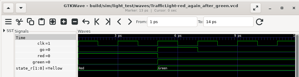
The screenshot was taken with GTKWave 3.3.116 on Linux, with the marker
placed at the end of the test. The .gtkw session file lists the ports of
the tested module and the state register state_r. A waveform file has no
notion of an enum, so the session also carries a table from each code to
its name: state_r reads Red, Green and Yellow instead of 00,
01, 10.
At the end of the test, state_r is Yellow, not Red. The design
spends four cycles in green and one in yellow; the test forgot the yellow
cycle. The design is right and the test is wrong. Change step(4) to
step(5) in the second test:
Replace this file: light_test.volt
// Simulation tests for TrafficLight.

test "go turns the light green" {
    let dut = TrafficLight { };
    dut.go = true;
    step(1);
    dut.go = false;
    assert_true(dut.green);
}

test "red again after green" {
    let dut = TrafficLight { };
    dut.go = true;
    step(1);
    dut.go = false;
    step(5);
    assert_true(dut.red);
}
Save the file and run the tests again:
Type this:
volt test
You should see:
   Compiling counter_test.volt
   Compiling light_test.volt
running 5 tests
note: Verilator not found locally; running it in Docker (verilator/verilator:v5.054)
test counts_while_enabled ... ok
test holds_while_disabled ... ok
test wraps_to_zero_after_MAX ... ok
test go_turns_the_light_green ... ok
test red_again_after_green ... ok

cover summary:
  Counter.cov_0 (counter.volt:26)                          hit 1 time
  TrafficLight.cov_0 (light.volt:21, auto FSM transition)  hit 2 times
  TrafficLight.cov_1 (light.volt:27, auto FSM transition)  hit 1 time
  TrafficLight.cov_2 (light.volt:33, auto FSM transition)  hit 1 time
  TrafficLight.cov_3 (light.volt:25, auto counter wrap)    hit 1 time

test result: ok. 5 passed; 0 failed
All tests pass. volt test --watch runs them again every time you save a
file.
Coming from SystemVerilog? Tests without a testbench file
A Volt test block compiles to a C++ Verilator testbench: step() toggles
every clock of the design, reset is applied before the test body, and the
contracts of the design run as monitors on every cycle. There is no initial block, no #delay and no
UVM. A passing run records no waveform, so it costs nothing; volt test --waves records every test. The .gtkw file and the translate tables are
extra files next to the VCD; the generated SystemVerilog does not change.
Volt builds the testbench with Verilator’s -fno-dfg option
(Known limitations says why).
Next: what we learned.
What we learned
A short look back at the Tour, and where the Tutorial picks up.
Before you start
- Window: none. This page has nothing to type.
- Folder: none. Your work is in
volt-projects: the projectblinkyand the single design incdc. - Running: nothing. You may close Docker Desktop until the next
volt test.
In Setup you installed a single binary and asked volt doctor what works
on your machine. Then, in about 15 minutes, you have:
- created a project with
volt new, checked it withvolt checkand turned it into readable SystemVerilog withvolt build; - written a design with two clock domains in a folder of its own, seen
the compiler reject a crossing without a synchronizer (
E3001), and fixed it withsync(); - run simulation tests with
volt test, with Verilator running in Docker, and read the cover summary; - followed a failing test to its waveform, where a state register shows the names of its states.
The commands you used:
| Command | What it does | Needs |
|---|---|---|
cd FOLDER | makes FOLDER the working folder of the terminal | nothing |
volt new NAME | creates a project from a template | nothing |
volt check | finds errors, writes no files | nothing |
volt build | writes SystemVerilog to build/rtl/ | nothing |
volt test | runs the test blocks of the project | Verilator, or Docker Desktop running |
volt explain CODE | explains an error code or a topic | nothing |
volt doctor | says which commands work here | nothing |
Two commands did not come up: volt verify, which proves contracts for
every input sequence, and volt run, which simulates a design without
tests. The Tutorial covers both.
Next
Part II, the Tutorial, starts again from a blank file and builds a counter line by line: modules, ports, registers, clocked blocks, bit widths and tests. Each later chapter adds one idea on top.
A counter
In this chapter you will write a counter from a blank file: a module
with ports, a register, a clocked on block and a continuous
assignment. You will learn how Volt decides the bit width of a result and
why it refuses to drop bits silently, and you will test the counter in
simulation.
The output in this chapter was recorded with Volt 0.1.0 on Windows 11, with Verilator running in Docker (see Install Volt).
A file of its own
A project with a Volt.toml is handy, but a single .volt file works too.
Make a new directory and create a file named counter.volt in it.
A module, ports and a register
// A free-running 8-bit counter.

pub module Counter {
    in  clk   : clock
    out count : u8

    reg count_r : u8 = 0

    on clk {
        count_r <= count_r + 1
    }

    count = count_r
}
Line by line:
pub module Counter { ... }declares a circuit namedCounter.publets other files use it; a chapter on projects with several files, still planned, comes back to that.in clk : clockandout count : u8are the ports: the wires that connect the module to the outside. Each port has a direction (inorout), a name and a type.clockis a clock input;u8is an unsigned number of 8 bits (0 to 255).boolis a single bit that istrueorfalse.reg count_r : u8 = 0declares a register: 8 bits of storage. The value after=is its reset value.on clk { ... }says what happens at each rising edge ofclk.count_r <= count_r + 1gives the register its next value.count = count_ris a continuous assignment: the outputcountalways shows the current value ofcount_r.
The _r suffix is a naming habit for registers, not a rule.
New to hardware? Clocks, flip-flops and reset
A clock is a signal that switches between 0 and 1 at a steady rate, for
example 50 million times a second. A flip-flop stores one bit and changes
it at the moment the clock rises, and at no other time. A register is a
row of flip-flops: count_r is eight of them. So the line
count_r <= count_r + 1 does not run in a loop; it describes an adder
whose output is stored at every clock edge. Reset is a separate input
that puts every register back to a known value, here 0, for example after
power-up.
Check the file:
Type this:
volt check counter.volt
You should see:
    Checking counter.volt
    Finished 0.00s
      Result 0 error(s), 0 warning(s)
       Next: volt build counter.volt   (emit SystemVerilog)
volt build counter.volt writes build/rtl/Counter.sv. The module part
of it:
module Counter (
    input  logic       clk,
    input  logic       rst,
    output logic [7:0] count
);

    logic [7:0] count_r;

    always_ff @(posedge clk) begin
        if (rst) begin
            count_r <= 8'd0;
        end else begin
            count_r <= count_r + 8'd1;
        end
    end

    assign count = count_r;

endmodule
The reset input rst was added for you: a module with a single clock gets
a synchronous, active-high reset, and every register returns to its reset
value while rst is high.
Coming from SystemVerilog? reg, on and the two kinds of assignment
A reg with its on block becomes one always_ff with the reset branch
generated from the initial value; there is no separate reset code to keep
in sync. <= is allowed inside an on block and nowhere else, and =
outside it: writing o = r inside on clk is error E0006. Unlike
Verilog’s reg keyword, a Volt reg is always a flip-flop.
Volt does not yet check that combinational logic assigns every output on
every path: an incomplete assignment in a comb block compiles, and the
always_comb it becomes infers a latch (see
Known limitations). This counter infers
no latch, because count is assigned on every path, by the assign
above.
Enable and step inputs
A counter that always runs is not very useful. Add an enable input, a
step input for the amount to add, and an output low with the lower four
bits of the count:
// An 8-bit counter that adds `step` on every clock edge while
// `enable` is high.

pub module Counter {
    in  clk    : clock
    in  enable : bool
    in  step   : u4
    out count  : u8
    out low    : u4

    reg count_r : u8 = 0

    on clk {
        if enable {
            count_r <= count_r + step
        }
    }

    count = count_r
    low   = count_r
}
if enable { ... } inside the on block means: at a clock edge, update
the register when enable is high, and keep its value otherwise.
This version has a mistake on purpose. Check it:
Type this:
volt check counter.volt
You should see:
    Checking counter.volt
error[E2001]: an 8-bit value does not fit in a 4-bit target
   ┌─ counter.volt:20:13
   │
20 │     low   = count_r
   │             ^^^^^^^ implicit narrowing is not allowed
   │
   = reason: narrowing drops the upper bits; in hardware that truncation must be visible
   = help: keep the low 4 bits explicitly: (expr)[3:0] as u4
   = for more: volt explain E2001


    Finished 0.00s
      Result 1 error(s), 0 warning(s)
Bit widths
Every value in Volt has a width, and Volt never drops bits without being told. The rules you need for now:
- An addition can grow by one bit.
count_r + stepadds an 8-bit and a 4-bit number; the exact sum needs up to 9 bits. Assigned to the 8-bit register, the sum keeps its lower 8 bits: the counter wraps from 255 back to a small number, which is what a counter should do. Assigned to a 9-bit target, the sum keeps its carry. Aletwithout a type keeps the carry too: withaandbbothu8,let sum = a + bis a 9-bit value. - A wider target is fine. A 12-bit output assigned
count_r + stepgets the operands widened to 12 bits before the addition. - A narrower target is an error.
lowhas 4 bits andcount_rhas 8. Copying one into the other would lose the upper 4 bits, so Volt asks you to say so (E2001). - Literals must fit.
reg r : u4 = 20is an error (E2010), because 4 bits hold at most 15.
The help line shows the fix: name the bits you want. count_r[3:0]
selects bits 3 down to 0; the result is bits<4>, four raw bits with no
number meaning, and as u4 reads them as a number. Nothing is dropped by
the cast, so there is no warning. (A plain count_r as u4 compiles too,
but warns with W2010: a narrowing cast can hide a mistake as well as
state an intent.)
// An 8-bit counter that adds `step` on every clock edge while
// `enable` is high.

pub module Counter {
    in  clk    : clock
    in  enable : bool
    in  step   : u4
    out count  : u8
    out low    : u4

    reg count_r : u8 = 0

    on clk {
        if enable {
            count_r <= count_r + step
        }
    }

    count = count_r
    low   = count_r[3:0] as u4
}
Type this:
volt check counter.volt
You should see:
    Checking counter.volt
    Finished 0.00s
      Result 0 error(s), 0 warning(s)
       Next: volt build counter.volt   (emit SystemVerilog)
The generated SystemVerilog makes each width explicit:
    always_ff @(posedge clk) begin
        if (rst) begin
            count_r <= 8'd0;
        end else begin
            if (enable) begin
                count_r <= count_r + 8'(step);
            end
        end
    end

    assign count = count_r;
    assign low = count_r[3:0];
Coming from SystemVerilog? No silent truncation or extension
SystemVerilog sizes an expression from its context and truncates or
zero-extends to fit: assign low = count_r; compiles, and a lint tool may
or may not warn. Volt makes narrowing an error and widening explicit in the
output (8'(step)), so verilator -Wall has nothing to say about
WIDTHEXPAND or WIDTHTRUNC. The sum of an addition may be assigned at
its operand width (it wraps, as a counter needs) or wider (it keeps the
carry); a narrower target needs a cast. Signed and unsigned never mix
implicitly (E2002).
Test it
Create counter_test.volt next to counter.volt. A file named
X_test.volt sees the modules of X.volt:
// Simulation tests for Counter.

test "counts by step while enabled" {
    let dut = Counter { };
    dut.enable = true;
    dut.step = 3;
    step(4);
    assert_eq(dut.count, 12);
    assert_eq(dut.low, 12);
}

test "holds while disabled" {
    let dut = Counter { };
    dut.step = 1;
    step(5);
    assert_eq(dut.count, 0);
}

test "wraps around after 255" {
    let dut = Counter { };
    dut.enable = true;
    dut.step = 15;
    step(17);
    assert_eq(dut.count, 255);
    assert_eq(dut.low, 15);
    step(1);
    assert_eq(dut.count, 14);
    assert_eq(dut.low, 14);
}
Each test starts a fresh counter with its reset applied (Counter { }).
Inputs not set by the test are 0, which is why the second test sees no
change: enable stays false. step(n) lets n clock edges pass. In the
last test, 17 steps of 15 reach 255, and one more step gives 270, which
wraps to 270 − 256 = 14.
Type this:
volt test counter_test.volt
You should see:
   Compiling counter_test.volt
running 3 tests
note: Verilator not found locally; running it in Docker (verilator/verilator:v5.054)
test counts_by_step_while_enabled ... ok
test holds_while_disabled ... ok
test wraps_around_after_255 ... ok

test result: ok. 3 passed; 0 failed
New to hardware? Why test with numbers that wrap
Hardware counters, timers and addresses have a fixed number of bits, and most bugs hide at the edges: the step from the largest value back to 0, or a value that is one too large for its field. A good test drives the design to those edges on purpose, as the last test does.
What we learned
- A
modulehas typedinandoutports;clock,bool,u8andbits<4>are types. reg name : type = valueis a register with its reset value;on clkupdates registers with<=;=outside it connects outputs.- Additions may wrap at the operand width or keep the carry one bit wider; narrowing is an error until you say which bits you want.
testblocks drive inputs, advance the clock withstep()and check outputs;volt testruns them in Verilator.
Next: a state machine with enum turns a sequence of steps into states.
A state machine with enum
You will turn a sequence of steps into a finite state machine: an enum for the states, a match for the transitions, and the checks Volt adds for you. The compiler requires every state to be handled, and generates a cover for every transition, so a test run shows which transitions your tests never took.
Before you start
-
Window: a terminal (how to open one) and your editor.
-
Folder: your
volt-projectsfolder. This chapter makes a new folder there,fsm. Type this:cd ~/volt-projects -
Running: for the sections from Test it on, Docker Desktop with Engine running in its window (Setup shows how):
volt testruns the Verilator simulator in Docker. If Verilator is installed on your computer, Docker is not needed;volt doctorsays which onevolt testuses.
The output on this page was recorded with Volt 0.1.0 in PowerShell on
Windows 11, with Docker Desktop running Verilator. On macOS and Linux,
paths are written with / instead of \.
A button that bounces
A push button does not switch cleanly. When you press it, the metal contacts bounce for a few milliseconds, and the input goes on and off many times before it stays on. A design that counts presses would count every bounce. A debouncer waits until the input has been steady for a while before it believes it.
The debouncer is a state machine: at any moment it is in one of a few named situations, its states, and at each clock edge it decides from its inputs whether to move to another state. Ours has four:
| State | Means | Moves on |
|---|---|---|
Up | the button is released | to GoingDown when the input is on |
GoingDown | the input is on, but not for long enough yet | to Down after a steady stretch, back to Up if the input drops |
Down | the button is pressed | to GoingUp when the input is off |
GoingUp | the input is off, but not for long enough yet | to Up after a steady stretch, back to Down if the input comes back |
Make a folder fsm and go into it:
Type this:
mkdir fsm
Type this:
cd fsm
States as an enum
In this folder, create the file debounce.volt (as
Setup shows). This version has a mistake on
purpose: one state is missing from the match.
Create this file: debounce.volt
// Cleans up a bouncing push button.

const STABLE : u4 = 4

enum Button { Up, GoingDown, Down, GoingUp }

pub module Debouncer {
    in  clk     : clock
    in  raw     : bool
    out pressed : bool
    out click   : bool

    reg state_r : Button = Button::Up
    reg count_r : u4     = 0

    on clk {
        match state_r {
            Button::Up => {
                if raw {
                    count_r <= 0
                    state_r <= Button::GoingDown
                }
            }
            Button::GoingDown => {
                if !raw {
                    state_r <= Button::Up
                } else if count_r == STABLE - 1 {
                    state_r <= Button::Down
                } else {
                    count_r <= count_r + 1
                }
            }
            Button::Down => {
                if !raw {
                    count_r <= 0
                    state_r <= Button::GoingUp
                }
            }
        }
    }

    pressed = state_r == Button::Down || state_r == Button::GoingUp
    click   = state_r == Button::GoingDown && raw && count_r == STABLE - 1
}
What is new compared with the counter:
const STABLE : u4 = 4names a constant: how many clock cycles the input must stay the same. A real button needs a few milliseconds, hundreds of thousands of cycles; 4 keeps the tests short.enum Button { Up, GoingDown, Down, GoingUp }declares a type whose values are the four states.Button::Upis one of them.reg state_r : Button = Button::Upis the state register. It holds one of the four values, and starts inUpafter reset.match state_r { ... }picks the arm for the current state. Each arm,Button::Up => { ... }, says what happens at the clock edge while the machine is in that state. A state that does not writestate_rstays where it is.count_rcounts how long the input has been steady. Each “going” state sets it to 0 on the way in and counts up; when it reachesSTABLE - 1, the machine moves on.pressedandclickare outputs computed from the state.==compares two enum values.clickis true for the one cycle in whichGoingDowndecides that the press is real: a single pulse per press, however long the button is held.
New to hardware? A state machine is a register and a decision
In software a sequence of steps is code that runs from top to bottom. In
hardware nothing runs from top to bottom: at every clock edge all the
logic is evaluated at once. To do one thing after another, the circuit
keeps a register that says which step it is at, and logic that picks the
next step from that register and the inputs. That pair is a finite
state machine (FSM). Naming the steps with an enum makes the register
readable: Button::GoingDown instead of the number 1.
Every state needs an arm
Check the file:
Type this:
volt check debounce.volt
You should see:
    Checking debounce.volt
error[E0014]: 'match' on enum 'Button' does not cover every variant: missing Button::GoingUp
   ┌─ debounce.volt:17:9
   │
17 │ ╭         match state_r {
18 │ │             Button::Up => {
19 │ │                 if raw {
20 │ │                     count_r <= 0
   · │
38 │ │             }
39 │ │         }
   │ ╰─────────^ not every variant is covered
   │
   = note: an enum match that names every variant needs no '_' arm; its last arm also takes the codes no variant uses
   = help: add an arm for each missing variant (Button::GoingUp => { }) or a final '_ => { }' arm
   = for more: volt explain E0014


    Finished 0.01s
      Result 1 error(s), 0 warning(s)
The match handles three of the four states, and error E0014 names
the one that is missing. In SystemVerilog, a case without that branch
would compile, and the machine would freeze in GoingUp the earliest
time it got there. Volt rejects it at compile time.
The help line offers two fixes: an arm for Button::GoingUp, or a final
_ => { } arm that catches every state not named above it. Prefer the
arm: with _, a state you add to the enum later is silently caught by
it, and the compiler can no longer tell you that you forgot it. Add the
missing arm:
Replace this file: debounce.volt
// Cleans up a bouncing push button.

const STABLE : u4 = 4

enum Button { Up, GoingDown, Down, GoingUp }

pub module Debouncer {
    in  clk     : clock
    in  raw     : bool
    out pressed : bool
    out click   : bool

    reg state_r : Button = Button::Up
    reg count_r : u4     = 0

    on clk {
        match state_r {
            Button::Up => {
                if raw {
                    count_r <= 0
                    state_r <= Button::GoingDown
                }
            }
            Button::GoingDown => {
                if !raw {
                    state_r <= Button::Up
                } else if count_r == STABLE - 1 {
                    state_r <= Button::Down
                } else {
                    count_r <= count_r + 1
                }
            }
            Button::Down => {
                if !raw {
                    count_r <= 0
                    state_r <= Button::GoingUp
                }
            }
            Button::GoingUp => {
                if raw {
                    state_r <= Button::Down
                } else if count_r == STABLE - 1 {
                    state_r <= Button::Up
                } else {
                    count_r <= count_r + 1
                }
            }
        }
    }

    pressed = state_r == Button::Down || state_r == Button::GoingUp
    click   = state_r == Button::GoingDown && raw && count_r == STABLE - 1
}
Type this:
volt check debounce.volt
You should see:
    Checking debounce.volt
    Finished 0.02s
      Result 0 error(s), 0 warning(s)
       Next: volt build debounce.volt   (emit SystemVerilog)
Test it
Create debounce_test.volt next to debounce.volt:
Create this file: debounce_test.volt
// Simulation tests for Debouncer.

test "a steady press is seen once" {
    let dut = Debouncer { };
    dut.raw = true;
    step(4);
    assert_false(dut.pressed);
    assert_true(dut.click);
    step(1);
    assert_true(dut.pressed);
    assert_false(dut.click);
    step(10);
    assert_true(dut.pressed);
    assert_false(dut.click);
}

test "a short bounce is ignored" {
    let dut = Debouncer { };
    dut.raw = true;
    step(2);
    dut.raw = false;
    step(1);
    dut.raw = true;
    step(2);
    dut.raw = false;
    step(5);
    assert_false(dut.pressed);
}

test "a release needs a steady low too" {
    let dut = Debouncer { };
    dut.raw = true;
    step(5);
    dut.raw = false;
    step(2);
    assert_true(dut.pressed);
    step(3);
    assert_false(dut.pressed);
}
The earliest test holds the button down. After 4 cycles the machine has
been in GoingDown long enough: click is on for that cycle, and from
the next one on the button counts as pressed. The second test presses
for two cycles, lets go, presses again and lets go: no stretch is long
enough, so pressed never turns on. The third test releases the button
and checks that pressed stays on until the release has been steady.
Check that Docker Desktop says Engine running, then run the tests:
Type this:
volt test debounce_test.volt
You should see:
   Compiling debounce_test.volt
running 3 tests
note: Verilator not found locally; running it in Docker (verilator/verilator:v5.054)
test a_steady_press_is_seen_once ... ok
test a_short_bounce_is_ignored ... ok
test a_release_needs_a_steady_low_too ... ok

cover summary:
  Debouncer.cov_0 (debounce.volt:21, auto FSM transition)  hit 4 times
  Debouncer.cov_1 (debounce.volt:26, auto FSM transition)  hit 2 times
  Debouncer.cov_2 (debounce.volt:28, auto FSM transition)  hit 2 times
  Debouncer.cov_3 (debounce.volt:36, auto FSM transition)  hit 1 time
  Debouncer.cov_4 (debounce.volt:41, auto FSM transition)  NEVER HIT
  Debouncer.cov_5 (debounce.volt:43, auto FSM transition)  hit 1 time
  Debouncer.cov_6 (debounce.volt:27, auto counter wrap)    hit 16 times

test result: ok. 3 passed; 0 failed
The three tests pass. Below them is a cover summary with seven lines,
although the design has no cover line. Volt found the state machine in
the match and generated a cover for every transition the code can
make, plus one for the counter. Each line names where the transition is
written, and how many cycles of the test run took it:
debounce.volt:21is the linestate_r <= Button::GoingDownin theUparm: the transition fromUptoGoingDown. It was taken 4 times, at least once in each test.debounce.volt:41is the linestate_r <= Button::Downin theGoingUparm: a bounce while the button is being released.NEVER HITmeans that no test made that transition, so it was never tested.auto counter wrapcounts the cycles in whichcount_rholds its largest value,STABLE - 1.
A transition no test took
Add a test for the bounce on release: hold the button, let go for a single cycle, press again. Replace the test file:
Replace this file: debounce_test.volt
// Simulation tests for Debouncer.

test "a steady press is seen once" {
    let dut = Debouncer { };
    dut.raw = true;
    step(4);
    assert_false(dut.pressed);
    assert_true(dut.click);
    step(1);
    assert_true(dut.pressed);
    assert_false(dut.click);
    step(10);
    assert_true(dut.pressed);
    assert_false(dut.click);
}

test "a short bounce is ignored" {
    let dut = Debouncer { };
    dut.raw = true;
    step(2);
    dut.raw = false;
    step(1);
    dut.raw = true;
    step(2);
    dut.raw = false;
    step(5);
    assert_false(dut.pressed);
}

test "a release needs a steady low too" {
    let dut = Debouncer { };
    dut.raw = true;
    step(5);
    dut.raw = false;
    step(2);
    assert_true(dut.pressed);
    step(3);
    assert_false(dut.pressed);
}

test "a bounce on release keeps the press" {
    let dut = Debouncer { };
    dut.raw = true;
    step(5);
    dut.raw = false;
    step(1);
    dut.raw = true;
    step(5);
    assert_true(dut.pressed);
    assert_false(dut.click);
}
Type this:
volt test debounce_test.volt
You should see:
   Compiling debounce_test.volt
running 4 tests
note: Verilator not found locally; running it in Docker (verilator/verilator:v5.054)
test a_steady_press_is_seen_once ... ok
test a_short_bounce_is_ignored ... ok
test a_release_needs_a_steady_low_too ... ok
test a_bounce_on_release_keeps_the_press ... ok

cover summary:
  Debouncer.cov_0 (debounce.volt:21, auto FSM transition)  hit 5 times
  Debouncer.cov_1 (debounce.volt:26, auto FSM transition)  hit 2 times
  Debouncer.cov_2 (debounce.volt:28, auto FSM transition)  hit 3 times
  Debouncer.cov_3 (debounce.volt:36, auto FSM transition)  hit 2 times
  Debouncer.cov_4 (debounce.volt:41, auto FSM transition)  hit 1 time
  Debouncer.cov_5 (debounce.volt:43, auto FSM transition)  hit 1 time
  Debouncer.cov_6 (debounce.volt:27, auto counter wrap)    hit 18 times

test result: ok. 4 passed; 0 failed
Every transition is now taken by at least one test. The last assert also
checks that the bounce did not produce a second click.
New to hardware? Why count transitions
A test that passes tells you that the design did what the test expected. It does not tell you what the test left out. In a state machine the rare paths, a bounce at the wrong moment or an error in the middle of a transfer, are the ones that break in the lab, and they are easy to forget. Counting the transitions turns “did I test everything?” into a list you can read.
The SystemVerilog
Type this:
volt build debounce.volt
You should see:
   Compiling debounce.volt
    Finished 0.01s (1 source file(s), 1 SV file(s))
     Output build\rtl\Debouncer.sv (72 lines)
       Next: volt run debounce.volt      (simulate)
             volt verify debounce.volt   (prove contracts)
Open build/rtl/Debouncer.sv (in the fsm folder) in your editor. This
is a part of it (output trimmed):
You should see:
    localparam logic [1:0] Button_Up        = 2'd0;
    localparam logic [1:0] Button_GoingDown = 2'd1;
    localparam logic [1:0] Button_Down      = 2'd2;
    localparam logic [1:0] Button_GoingUp   = 2'd3;

    logic [1:0] state_r;  // Button
...
            case (state_r)
                Button_Up: begin
                    if (raw) begin
                        count_r <= 4'd0;
                        state_r <= Button_GoingDown;
                    end
                end
...
                default: begin // Button_GoingUp
Each state becomes a localparam with the state’s name, numbered in the
order of the enum, and the match becomes a case. The arm of the
last state is the default branch, with its name in a comment: a value
that names no state, which cannot happen here, is handled like
GoingUp.
Coming from SystemVerilog? What the compiler checks for you
In SystemVerilog an FSM is usually a typedef enum, a case with a
default, and a lint rule or a review to catch a missing state. Volt
makes the missing arm a compile error (E0014) and writes no
typedef: the states are localparams, so the output reads the same in
every tool. The generated transition covers are SVA cover property
statements in volt build --emit=sva, and volt test counts them in
simulation. When the states do not fill the bits of the register, for
example three states in two bits, Volt also generates an invariant that
the register holds a valid state; the four states here use all four
codes. The waveform of a failed test shows the state names, as in
Tests and waveforms.
You are in the fsm folder.
What we learned
enum Name { A, B, C }declares the states; aregof that type,reg state_r : Name = Name::A, is the state register, with a state as its reset value.matchon the state register gives each state an arm; an arm that does not write the register keeps the state.- A
matchmust handle every state: a missing one is errorE0014. Prefer an arm per state over a_arm. constnames a number, such as how long an input must stay steady.- Volt generates a cover for every transition, and
volt testlists them:NEVER HITpoints at a transition no test took.
Next: two clocks and CDC moves data between parts of a design that run on different clocks.
Two clocks and CDC
You will declare clock domains, see why a signal cannot simply cross from one to another, and use sync() and AsyncFifo to cross safely. The chapter also covers resets in a design with several clocks.
Before you start
-
Window: a terminal (how to open one) and your editor.
-
Folder: your
volt-projectsfolder. This chapter makes a new folder there,clocks. Type this:cd ~/volt-projects -
Running: for the section Test it, Docker Desktop with Engine running in its window (Setup shows how):
volt testruns the Verilator simulator in Docker. If Verilator is installed on your computer, Docker is not needed;volt doctorsays which onevolt testuses. The other sections need nothing but Volt.
The output on this page was recorded with Volt 0.1.0 in PowerShell on
Windows 11, with Docker Desktop running Verilator. On macOS and Linux,
paths are written with / instead of \.
Two clocks, two domains
The Tour moved a single bit, a button, from one clock to another. This chapter moves numbers. A sensor chip, here an analog-to-digital converter (ADC), delivers 8-bit samples with a clock of its own; the rest of the design runs on the system clock. Each clock, with the registers it drives, is a clock domain. The samples have to cross from the ADC domain into the system domain.
Make a folder clocks and go into it:
Type this:
mkdir clocks
Type this:
cd clocks
In this folder, create the file sample_bridge.volt (as
Setup shows). This version keeps the latest
sample in a register of the ADC domain and copies it into a register of
the system domain:
Create this file: sample_bridge.volt
// Samples from a sensor clock reach the system clock.

domain Adc {
    clock = posedge
    reset = sync active_high
}

domain Sys {
    clock = posedge
    reset = sync active_high
}

pub module SampleBridge {
    in  adc_clk      : clock @Adc
    in  sys_clk      : clock @Sys
    in  rst          : reset(sync, active_high)
    in  sample       : u8    @Adc
    in  sample_valid : bool  @Adc
    out data         : u8    @Sys

    reg last_r : u8 = 0
    on adc_clk {
        if sample_valid {
            last_r <= sample
        }
    }

    reg data_r : u8 = 0
    on sys_clk {
        data_r <= last_r
    }

    data = data_r
}
What is new compared with the counter:
- A
domainblock names a clock domain and says how its registers work.clock = posedgemeans they update on the rising edge of the clock.reset = sync active_highmeans their reset is synchronous, read at a clock edge like any other input, and active high: 1 means reset. @Adcafter a port type puts the port into the domainAdc. The clock portadc_clkis the clock of that domain.- A register belongs to the domain of the
onblock that writes it:last_rtoAdc,data_rtoSys. in rst : reset(sync, active_high)is the reset input of the design. Reset with two clocks below explains why it is written out here, while the counter got its reset without asking.
A design with a single clock needs no domain at all; Volt puts
everything into one domain by itself.
This design is wrong on purpose. Check it:
Type this:
volt check sample_bridge.volt
You should see:
    Checking sample_bridge.volt
error[E3001]: direct assignment between clock domains
   ┌─ sample_bridge.volt:30:9
   │
 3 │ domain Adc {
   │        --- source @Adc defined here
   ·
 8 │ domain Sys {
   │        --- destination @Sys defined here
   ·
30 │         data_r <= last_r
   │         ^^^^^^    ------ @Adc
   │         │
   │         @Sys
   │
   = reason: the destination register may sample the source signal during an unstable window (metastability)
   = note: for multi-bit data, AsyncFifo may be safer
   = help: synchronize at module level, outside this block: let s = sync(<signal>, <clock of Sys>), then read s here
   = for more: volt explain E3001


    Finished 0.01s
      Result 1 error(s), 0 warning(s)
Line 30 reads last_r, a register of Adc, in an on sys_clk block of
Sys. That is a clock domain crossing (CDC) without a synchronizer,
error E3001. The note line already points to the way out for a number:
AsyncFifo. The next section shows why the sync() of the Tour is not
enough here.
Why sync() is not enough for a number
sync() builds a two-flop synchronizer for each bit. Do what the help
line suggests: synchronize last_r at module level and read the
synchronized name in the on sys_clk block. Replace the file:
Replace this file: sample_bridge.volt
// Samples from a sensor clock reach the system clock.

domain Adc {
    clock = posedge
    reset = sync active_high
}

domain Sys {
    clock = posedge
    reset = sync active_high
}

pub module SampleBridge {
    in  adc_clk      : clock @Adc
    in  sys_clk      : clock @Sys
    in  rst          : reset(sync, active_high)
    in  sample       : u8    @Adc
    in  sample_valid : bool  @Adc
    out data         : u8    @Sys

    reg last_r : u8 = 0
    on adc_clk {
        if sample_valid {
            last_r <= sample
        }
    }

    let last_s = sync(last_r, sys_clk)

    reg data_r : u8 = 0
    on sys_clk {
        data_r <= last_s
    }

    data = data_r
}
Type this:
volt check sample_bridge.volt
You should see:
    Checking sample_bridge.volt
warning[W3003]: two-flop synchronization does not guarantee bit coherence for 8-bit signals
   ┌─ sample_bridge.volt:28:18
   │
28 │     let last_s = sync(last_r, sys_clk)
   │                  ^^^^^^^^^^^^^^^^^^^^^ bits may be captured on different edges
   │
   = reason: a two-flop synchronizer synchronizes each bit independently; when bits are captured on different clock edges an invalid intermediate value appears
   = help: for multi-bit data use one of:
                AsyncFifo<T, N>   — data streams
                HandshakeSync<T>  — single transfers
                gray coding       — counters
                AsyncDualPortRam<T, N> — random-access data
   = for more: volt explain W3003


    Finished 0.01s
      Result 0 error(s), 1 warning(s)
       Next: volt build sample_bridge.volt   (emit SystemVerilog)
The design compiles now, with warning W3003: eight synchronizers side
by side do not keep the eight bits together.
New to hardware? Why the bits of a number fall apart
Each synchronizer settles on its own. When last_r goes from 127
(0111_1111) to 128 (1000_0000), all eight bits change at once. If
the system clock samples during the change, some synchronizers pass the
new bit one cycle before the others, and for that cycle the system
domain sees a mix of old and new bits: 255, 0, or any other value that
last_r never held. A single bit has no such problem: it is either old
or new.
It is a warning and not an error because some values survive it: a counter in Gray code changes one bit at a time, and a setting that is written once and read much later has long settled. For a stream of samples, use a FIFO.
A FIFO between the clocks
AsyncFifo is a built-in component: a small memory written on one clock
and read on the other, with the synchronizers it needs inside. Every
sample goes in on the ADC side and comes out on the system side, in the
same order. This version of the design also says when data holds a new
sample (data_valid), and when a sample was lost because the FIFO was
full (dropped). Replace the file:
Replace this file: sample_bridge.volt
// Samples from a sensor clock reach the system clock.

domain Adc {
    clock = posedge
    reset = sync active_high
}

domain Sys {
    clock = posedge
    reset = sync active_high
}

pub module SampleBridge {
    in  adc_clk      : clock @Adc
    in  sys_clk      : clock @Sys
    in  rst          : reset(sync, active_high)
    in  sample       : u8    @Adc
    in  sample_valid : bool  @Adc
    out data         : u8    @Sys
    out data_valid   : bool  @Sys
    out dropped      : bool  @Adc

    wire take : bool @Sys

    let fifo = AsyncFifo<u8, 4> {
        wr_clk:  adc_clk,
        wr_data: sample,
        wr_en:   sample_valid,
        rd_clk:  sys_clk,
        rd_en:   take,
    }

    take = !fifo.rd_empty

    reg valid_r : bool = false
    on sys_clk {
        valid_r <= take
    }

    data       = fifo.rd_data
    data_valid = valid_r
    dropped    = sample_valid && fifo.wr_full
}
Type this:
volt check sample_bridge.volt
You should see:
    Checking sample_bridge.volt
    Finished 0.01s
      Result 0 error(s), 0 warning(s)
       Next: volt build sample_bridge.volt   (emit SystemVerilog)
How it works:
AsyncFifo<u8, 4>holds up to 4 values of typeu8. The size must be a power of two.- The ports that start with
wr_belong to the domain ofwr_clk, hereAdc; the ports that start withrd_belong to the domain ofrd_clk,Sys. Volt checks what you connect:sampleis@Adcand goes towr_data. Connectingsample_validtord_enwould be errorE3001again. fifo.rd_emptyis true when there is nothing to read, andfifo.wr_fullis true when there is no room. The read side reads whenever the FIFO is not empty:take = !fifo.rd_empty.wire take : bool @Sysdeclares the wire, with its domain, above the FIFO, because a name must be declared before it is used (errorE1002). Its value is given further down. The@Sysis a promise that Volt checks: assigning it a value ofAdcwould be an error.fifo.rd_datais a register: a value read withrd_enappears on it one clock cycle later.valid_rdelaystakeby the same cycle, sodata_validis true exactly whendataholds a new sample.droppedis in theAdcdomain, because both of its inputs are.
Coming from SystemVerilog? A dual-clock FIFO without an IP core
In SystemVerilog you would instantiate a vendor FIFO generator or a
hand-written FIFO with Gray-coded pointers, and a CDC tool would be told
to trust it. AsyncFifo is generated into the module itself: Gray-coded
read and write pointers, a two-flop synchronizer for each pointer, and a
comment that names the crossing. The compiler knows which side belongs
to which domain, so the crossing is checked like any other. Other
built-in bridges: HandshakeSync for a single word now and then,
PulseSync for a one-cycle pulse, AsyncDualPortRam for a memory
(volt explain stdlib).
Reset with two clocks
A reset has to be released in step with the clock of every register it resets. With one clock that is easy. With two, the moment the reset goes away may be right on an edge of one clock while it is far from the edges of the other.
The line in rst : reset(sync, active_high) declares the reset as a
raw input: it comes from outside and is in step with neither clock.
For a raw reset, Volt builds one reset synchronizer for each clock that
it reaches, two flip-flops that pass the release on in step with that
clock. Each domain is then reset from its own copy.
Without that line, Volt still adds a reset port named rst, as for the
counter, but it cannot know which clock the reset is in step with, and
volt check warns:
You should see (if the rst line is missing):
Keep the line. The recipe Reset synchronizers shows the generated synchronizers, asynchronous resets and the related errors.
Test it
Create sample_bridge_test.volt next to sample_bridge.volt:
Create this file: sample_bridge_test.volt
// Simulation tests for SampleBridge. The test bench drives every clock
// of the design together, one edge per step().

test "samples cross in order" {
    let dut = SampleBridge { };
    dut.sample_valid = true;
    dut.sample = 10;
    step(1);
    dut.sample = 20;
    step(1);
    dut.sample = 30;
    step(1);
    dut.sample_valid = false;
    assert_false(dut.data_valid);
    step(1);
    assert_true(dut.data_valid);
    assert_eq(dut.data, 10);
    step(1);
    assert_eq(dut.data, 20);
    step(1);
    assert_eq(dut.data, 30);
    step(1);
    assert_false(dut.data_valid);
}

test "a full FIFO drops samples" {
    let dut = SampleBridge { };
    dut.sample_valid = true;
    step(3);
    assert_false(dut.dropped);
    step(1);
    assert_true(dut.dropped);
}
The test bench drives both clocks together: step(1) gives one rising
edge to adc_clk and one to sys_clk. The tests cannot run the two
clocks at different speeds, so they do not show the timing problems a
synchronizer protects against. What they show is the order of the
samples and how long a crossing takes. In the earliest test, the sample
10 is written on edge 1 and is on data after edge 4: the write pointer
has to pass a synchronizer before the read side sees it, and the read
itself takes a cycle. In the second test a sample arrives on every edge.
After four of them the write side sees the FIFO as full, because it
learns about the reads through a synchronizer too, and dropped turns
on: the next sample would be lost.
Check that Docker Desktop says Engine running, then run the tests:
Type this:
volt test sample_bridge_test.volt
You should see:
   Compiling sample_bridge_test.volt
running 2 tests
note: Verilator not found locally; running it in Docker (verilator/verilator:v5.054)
test samples_cross_in_order ... ok
test a_full_FIFO_drops_samples ... ok

cover summary:
  SampleBridge.fifo_cov_0 (sample_bridge.volt:25)  hit 1 time
  SampleBridge.fifo_cov_1 (sample_bridge.volt:25)  hit 10 times

test result: ok. 2 passed; 0 failed
The cover summary lists two covers that you did not write: AsyncFifo
brings them along, which is why both point to line 25, the let fifo
line. fifo_cov_0 counts the cycles in which the FIFO was full,
fifo_cov_1 those in which it was empty. Both were reached, so the
tests drove the FIFO to both of its limits.
The SystemVerilog
Type this:
volt build sample_bridge.volt
You should see:
   Compiling sample_bridge.volt
    Finished 0.01s (1 source file(s), 1 SV file(s))
     Output build\rtl\SampleBridge.sv (127 lines)
       Next: volt run sample_bridge.volt      (simulate)
             volt verify sample_bridge.volt   (prove contracts)
build/rtl/SampleBridge.sv holds one module, with the FIFO and the reset
synchronizers inside. These comment lines in it name each part (output
trimmed):
You should see:
    // reset synchronizer: rst -> adc_clk (async assert, sync release)
    // reset synchronizer: rst -> sys_clk (async assert, sync release)
    // AsyncFifo 'fifo': adc_clk -> sys_clk, depth 4 (gray-code pointers)
You are in the clocks folder.
What we learned
- A
domainnames a clock domain;@Nameputs a port or a wire into it, and a register belongs to the domain of itsonblock. - Reading a signal of one domain in another is error
E3001. sync()is for a single bit. On a number it is warningW3003, because the bits can arrive in different cycles.AsyncFifocarries a stream of values between two clocks; itswr_andrd_ports belong to the two domains.- A raw reset port,
in rst : reset(...), gets one reset synchronizer per clock. volt testdrives every clock together, one edge perstep().
Next: contracts and formal verification prove properties of a design for every input, not just the ones a test tries.
Contracts and formal verification
You will state properties of a design with invariant, requires, ensures and cover, and prove them for every input sequence with volt verify. You will read a counterexample and learn when bounded checking is enough and when you need a proof.
Before you start
-
Window: a terminal (how to open one) and your editor.
-
Folder: your
volt-projectsfolder. This chapter makes a new folder there,formal. Type this:cd ~/volt-projects -
Running:
volt verifyneeds three tools that Volt does not bring along: Yosys, SymbiYosys and an SMT solver.- Windows: these tools do not run on Windows by themselves. Start
Docker Desktop and wait for Engine running in its window
(Setup shows how).
Volt then runs the tools in a container. The container image is
downloaded the earliest time you run
volt verify: about 400 MB, which takes a few minutes. - macOS and Linux: Docker Desktop works the same way. Instead, you
can install the tools: the YosysHQ OSS CAD Suite has all three in one
download (
volt explain verify-setupsays where to get it).
volt doctorshows howvolt verifywill run: with Docker Desktop running, its line reads✓ verify — via Docker. - Windows: these tools do not run on Windows by themselves. Start
Docker Desktop and wait for Engine running in its window
(Setup shows how).
Volt then runs the tools in a container. The container image is
downloaded the earliest time you run
The output on this page was recorded with Volt 0.1.0 in PowerShell on
Windows 11, with Docker Desktop running the tools. On macOS and Linux,
paths are written with / instead of \.
Tests try some inputs, a proof tries all
The counter chapter tested a design: the test chose the inputs, cycle by cycle, and checked the outputs. A test shows that the design works for those inputs. It says nothing about the inputs nobody thought of.
A contract is a property written into the design itself, such as “the level never goes above 4”. Formal verification asks a solver, a program that searches through every possible input sequence, whether any of them breaks the contract. If one does, you get that input sequence as a counterexample, cycle by cycle. If none does, the property holds for every input the solver could choose.
Volt has four kinds of contract:
| Keyword | Means | May read |
|---|---|---|
invariant: | always true | ports and registers |
requires: | what the module expects from the module that uses it | ports |
ensures: | what the module promises in return | ports |
cover: | something that must be able to happen | everything |
volt verify checks them with formal verification. volt test checks
them too, while a test runs.
A buffer with four slots
Make a folder formal and go into it:
Type this:
mkdir formal
Type this:
cd formal
The design keeps count of the items in a buffer with four slots: push
puts an item in, pop takes one out. Create the file occupancy.volt
(as Setup shows):
Create this file: occupancy.volt
// Keeps count of the items in a buffer with four slots.

pub module Occupancy {
    in  clk   : clock
    in  push  : bool
    in  pop   : bool
    out level : u3
    out full  : bool
    out empty : bool

    reg level_r : u3 = 0

    on clk {
        if push && !pop {
            level_r <= level_r + 1
        } else if pop && !push {
            level_r <= level_r - 1
        }
    }

    level = level_r
    full  = level_r == 4
    empty = level_r == 0

    invariant: level_r <= 4
    cover: full
}
The two lines at the bottom are contracts:
invariant: level_r <= 4says that the register never holds more than 4.level_rhas 3 bits and could hold up to 7.cover: fullsays that the buffer can become full. A cover is not a promise that something always happens, but that it can happen at all; Covers below shows why that matters.
push and pop together leave the level as it is: one item goes in and
one comes out.
Check that Docker Desktop says Engine running, then verify the design. This takes a few minutes the earliest time, because of the download:
Type this:
volt verify occupancy.volt
You should see:
   Verifying occupancy.volt
note: SymbiYosys not found locally; running it in Docker (hdlc/formal:all)
note: downloading hdlc/formal:all (~404 MB, first use only; this can take several minutes)
note: downloaded hdlc/formal:all in 1m 18s
     [1/1] Occupancy (2 properties) ... FAIL (0.28s)
error[E5001]: contract violated
   ┌─ occupancy.volt:25:16
   │
25 │     invariant: level_r <= 4
   │                ^^^^^^^^^^^^ violated at cycle 3
   │
   = reason: the 'invariant' contract of module 'Occupancy' does not hold for every reachable state
   = counterexample: build\formal\occupancy_cex.vcd
   = help: open the counterexample with 'gtkwave' or 'surfer'
   = for more: volt explain E5001


    Finished 83.09s
    Failures:
      Occupancy.inv_0  E5001 contract violated at cycle 3
      Result 1 of 2 properties failed in 83.1s (16 jobs; bmc, depth 20)
        Next: volt explain E5001   (how to read a counterexample)
The two downloading notes appear once. This run took 83 seconds, almost
all of it for the download; the runs after it take about a second and a
half.
The invariant is violated. volt verify exits with code 6 and writes the
counterexample to build\formal\occupancy_cex.vcd. The summary line
counts two properties, the invariant and the cover, and says how the
search was made: bmc, depth 20 means the solver looked at the 20 clock
cycles after reset (the next sections explain the other modes). 16 jobs is the number of processor cores of the recording computer; your
number may differ.
Read the counterexample
A counterexample is a waveform, like the ones a failing test writes.
Open it in GTKWave (Tests and waveforms
shows how to install it), from the formal folder:
Type this (Windows, PowerShell):
gtkwave build\formal\occupancy_cex.vcd
Type this (macOS and Linux):
gtkwave build/formal/occupancy_cex.vcd
In GTKWave, open Occupancy in the tree at the top left and add the
signals to the view. Add smt_step from the top of the tree as well: it
numbers the clock cycles of the counterexample from 0.
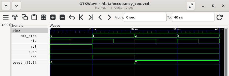
The screenshot was taken with GTKWave 3.3.121 on Linux (Debian 13). Read it cycle by cycle:
- Cycle 0:
rstis 1. The solver always starts from reset, solevel_ris 0. - Cycle 1:
popis 1 andpushis 0, while the buffer is empty. - Cycle 2:
level_ris 7.0 - 1wrapped around in 3 bits.
The invariant is checked at each clock edge, so the error names the edge after cycle 2: cycle 3. The design itself does what it says. The mistake is in what it allows: nothing stops a pop from an empty buffer, or a push into a full one.
New to hardware? Why a test would miss this
A test that pops an empty buffer would find this bug at once, but you have to think of writing that test. The solver does not think about what is sensible: it tries every input, including the ones a careful user would never send, and here it needed two cycles to find one. That is why formal verification is good at finding the cases nobody wrote a test for.
Requires and ensures
There are two ways to fix this. The design could ignore a pop from an
empty buffer. Or the module can say that it is never asked to do that,
and leave the duty to the module that uses it. That is what requires
is for. Replace the file:
Replace this file: occupancy.volt
// Keeps count of the items in a buffer with four slots.

pub module Occupancy {
    in  clk   : clock
    in  push  : bool
    in  pop   : bool
    out level : u3
    out full  : bool
    out empty : bool

    // The module that uses Occupancy promises these.
    requires: !(push && full)
    requires: !(pop && empty)

    reg level_r : u3 = 0

    on clk {
        if push && !pop {
            level_r <= level_r + 1
        } else if pop && !push {
            level_r <= level_r - 1
        }
    }

    level = level_r
    full  = level_r == 4
    empty = level_r == 0

    invariant: level_r <= 4
    ensures: prev(push) && !prev(pop) -> (level as u4) == prev(level) + 1
    cover: full
}
What changed:
requires: !(push && full)andrequires: !(pop && empty): no push while the buffer is full, no pop while it is empty. WhileOccupancyis verified, these are taken as given: the solver chooses no input that breaks them.ensures: ... -> ...is a promise about the outputs.a -> breads “ifa, thenb”.prev(x)is the valuexhad one cycle earlier, andprev(x, 2)two cycles earlier. The line says: after a cycle with a push and no pop, the level is exactly one higher than it was.level as u4makeslevelone bit wider, for the reason below.
An addition keeps its carry: prev(level) + 1 is a 4-bit value, because
3 bits plus one can need a fourth bit (7 + 1 = 8). Compared with the
3-bit level, the comparison could drop that carry, wrapping at 3 bits,
or keep it, and the two answers differ when the sum does not fit. Volt
does not guess: written as level == prev(level) + 1, the line is error
E2031, and the error offers both ways to write it:
level == (prev(level) + 1)[2:0] as u3keeps the low 3 bits of the sum: it wraps at 3 bits, so 7 + 1 counts as 0;(level as u4) == prev(level) + 1widenslevelto 4 bits: it keeps the carry, so 7 + 1 is 8.
Here the carry is kept: the level counts items and never wraps, and the
ensures should say so.
Type this:
volt verify occupancy.volt
You should see:
   Verifying occupancy.volt
note: SymbiYosys not found locally; running it in Docker (hdlc/formal:all)
     [1/1] Occupancy (3 properties, 2 assumed) ... ok (0.26s)
    Finished 1.28s
        Note 2 assumption(s) about the environment, not verified: Occupancy.req_0, Occupancy.req_1
      Result 3 properties verified in 1.3s (16 jobs; bmc, depth 20)
All three properties hold. The Note line lists the two requires:
they were assumed, not checked, because nothing in this file uses
Occupancy. When another module uses it, volt verify on that module
checks them there, as properties of the module that has to keep them.
Covers: can it happen at all?
A requires that is too strict makes every check pass for a bad reason.
Suppose the upper requires read requires: !push: the solver may then
never push, the buffer stays empty, and the invariant holds, without
saying anything about a buffer that is in use. A cover catches this.
Verify again in cover mode:
Type this:
volt verify --mode cover occupancy.volt
You should see:
   Verifying occupancy.volt
note: SymbiYosys not found locally; running it in Docker (hdlc/formal:all)
     [1/1] Occupancy (3 properties, 2 assumed) ... ok (0.20s)
    Finished 1.20s
        Note 2 assumption(s) about the environment, not verified: Occupancy.req_0, Occupancy.req_1
      Result 3 properties verified in 1.2s (16 jobs; cover, depth 20)
In cover mode the solver searches for a way to reach each cover within
the depth. It found one for cover: full, so the buffer can fill up
while the requires hold. With requires: !push in place of the upper
requires, the same command reports the cover as an error:
You should see (with requires: !push):
In cover mode the error means “not reached within the depth”: the solver
searched the 20 cycles of the depth and found no way to make full
true; the cycle in the message is the last one it searched. The words
of the message are the ones used for a broken property (“violated”,
“does not hold”), and no counterexample file is written, although the
help line names one; volt explain E5001 describes both modes. Run
--mode cover whenever you add or change a requires.
Twenty cycles, or every cycle
So far volt verify ran in its default mode, bmc (bounded model
checking): the solver looked for a counterexample within 20 cycles after
reset. That is enough for Occupancy, which reaches each of its levels
within a few cycles. It is not enough for a design that needs more
cycles to go wrong.
This module gives a pulse every 25 cycles, and has a bug: it counts to
25 instead of 24, so the count reaches 25 for one cycle. Create
divider.volt:
Create this file: divider.volt
// Gives a one-cycle tick every 25 clock cycles.

pub module Divider {
    in  clk  : clock
    out tick : bool

    reg count_r : u5 = 0

    on clk {
        if count_r == 25 {
            count_r <= 0
        } else {
            count_r <= count_r + 1
        }
    }

    tick = count_r == 24

    invariant: count_r < 25
}
Type this:
volt verify divider.volt
You should see:
   Verifying divider.volt
note: SymbiYosys not found locally; running it in Docker (hdlc/formal:all)
     [1/1] Divider (3 properties) ... ok (0.24s)
    Finished 1.28s
      Result 3 properties verified in 1.3s (16 jobs; bmc, depth 20)
Every property holds, because the count reaches 25 after more than 20 cycles. The design has three properties although you wrote one: for a counter, Volt adds an upper bound and a cover of its wrap by itself.
A passing bmc run says: no counterexample within 20 cycles. To know
about every cycle, ask for a proof:
Type this:
volt verify --mode prove divider.volt
You should see:
   Verifying divider.volt
note: SymbiYosys not found locally; running it in Docker (hdlc/formal:all)
     [1/1] Divider (3 properties) ... unknown (0.26s)
error[E5002]: contract not proven: the induction step failed
   ┌─ divider.volt:19:16
   │
19 │     invariant: count_r < 25
   │                ^^^^^^^^^^^^ not inductive at depth 20
   │
   = reason: no counterexample exists within 20 cycles from reset, but the induction step starts from an arbitrary state — possibly unreachable — and the 'invariant' contract of module 'Divider' fails from there (sby status UNKNOWN)
   = note: induction trace (may start from an unreachable state): build\formal\divider_induct.vcd
   = help: try a larger --depth, or add an invariant that makes the property inductive
   = for more: volt explain E5002


    Finished 1.29s
    Failures:
      Divider.inv_0  E5002 not proven (induction step failed)
      Result 0 of 3 properties failed, 1 not proven in 1.3s (16 jobs; prove, depth 20)
        Next: volt explain E5002   (why a true property can fail induction)
--mode prove uses induction: if the property held for 20 cycles in a
row, starting anywhere, does it hold in the next one? Here it does not,
so the proof fails, and the command exits with code 7, “not proven”. That
is not yet a bug: the solver may have started from a state the design
can never reach. The help line names the two ways on. A larger depth
looks further:
Type this:
volt verify --depth 30 divider.volt
You should see:
   Verifying divider.volt
note: SymbiYosys not found locally; running it in Docker (hdlc/formal:all)
     [1/1] Divider (3 properties) ... FAIL (0.27s)
error[E5001]: contract violated
   ┌─ divider.volt:19:16
   │
19 │     invariant: count_r < 25
   │                ^^^^^^^^^^^^ violated at cycle 27
   │
   = reason: the 'invariant' contract of module 'Divider' does not hold for every reachable state
   = counterexample: build\formal\divider_cex.vcd
   = help: open the counterexample with 'gtkwave' or 'surfer'
   = for more: volt explain E5001


    Finished 1.34s
    Failures:
      Divider.inv_0  E5001 contract violated at cycle 27
      Result 1 of 3 properties failed in 1.3s (16 jobs; bmc, depth 30)
        Next: volt explain E5001   (how to read a counterexample)
Now bmc finds the bug, at cycle 27. Fix the comparison,
count_r == 24:
Replace this file: divider.volt
// Gives a one-cycle tick every 25 clock cycles.

pub module Divider {
    in  clk  : clock
    out tick : bool

    reg count_r : u5 = 0

    on clk {
        if count_r == 24 {
            count_r <= 0
        } else {
            count_r <= count_r + 1
        }
    }

    tick = count_r == 24

    invariant: count_r < 25
}
Type this:
volt verify --mode prove divider.volt
You should see:
   Verifying divider.volt
note: SymbiYosys not found locally; running it in Docker (hdlc/formal:all)
     [1/1] Divider (3 properties) ... ok (0.22s)
    Finished 1.26s
      Result 3 properties verified in 1.3s (16 jobs; prove, depth 20)
Proved: the invariant holds in every cycle, however long the design runs. When to use which mode:
bmc(the default) finds bugs that happen within--depthcycles of reset, and gives a counterexample. It is enough when the design reaches all of its states within that depth.--mode proveshows that a property holds forever. Use it for counters, timers and anything else that takes many cycles to come back to where it started. When it says “not proven”, try a larger--depth, or add aninvariantthat rules out the states the solver started from.--mode covershows that the covers can be reached, so that a passing proof is not passing because nothing can happen.
You are in the formal folder.
Coming from SystemVerilog? Contracts become SVA
volt build --emit=sva writes the contracts as SystemVerilog
assertions in build/formal/, in a checker module with a bind. An
invariant becomes an assert property with @(posedge clk) disable iff (rst), a requires becomes an assume property while the module
itself is verified, prev(x, N) becomes $past(x, N), and a -> b
becomes a |-> b. volt verify writes the SymbiYosys script for you
and maps a failure back to the line of the contract. There are no
sequences (##) and no liveness properties; see
Known limitations.
What we learned
invariant,requires,ensuresandcoverare written into the module;prev(x)reads the value of the previous cycle,a -> breads “if a, then b”.volt verifyexits with code 6 and writes a counterexample waveform when a contract can be broken; read it cycle by cycle.- A
requiresis assumed while its module is verified and checked where the module is used. --mode covershows that the covers can happen, so a too strictrequiresdoes not go unnoticed.bmclooks--depthcycles deep;--mode provecovers every cycle, and says “not proven” (code 7) when induction is not enough.
Next: the chapters after this one in the Tutorial are planned. The Cookbook has recipes that build on this chapter and the previous one, such as Reset synchronizers.
A UART transmitter
You will build a complete serial transmitter from the counter and the state machine of the earlier chapters. The chapter covers constants, bit timing, shifting data out, and a handshake with the rest of the design.
This chapter is planned. It will be written after feedback on the Tour and the counter chapter. Until then, these show the same topic:
Tests
You will write simulation tests beyond the basics: loops, let bindings, loading memory from a hex file, and tests for designs with several clocks. You will also see how contracts run as monitors in every test.
This chapter is planned. It will be written after feedback on the Tour and the counter chapter. Until then, these show the same topic:
- A counter and Tests and waveforms:
testblocks,step()and asserts- Two clocks and CDC: a test of a design with two clocks
- ADR-0033: test blocks
- ADR-0058: the extended test language
- ADR-0064: contracts in simulation
- examples/riscv_core_test.volt
Waveforms
You will record waveforms from tests and from volt run, open them in GTKWave with enum names, and find a bug by reading signals cycle by cycle.
This chapter is planned. It will be written after feedback on the Tour and the counter chapter. Until then, these show the same topic:
- Tests and waveforms: the waveform of a failing test in GTKWave, with state names
- Contracts and formal verification: reading a counterexample waveform
- ADR-0092: enum names in waveforms
- ADR-0095: waveforms of failed tests
volt explain waveforms
A multi-file project
You will split a design into several files, import modules and functions with use, and choose the top module in Volt.toml. The chapter ends with a small system on a chip.
This chapter is planned. It will be written after feedback on the Tour and the counter chapter. Until then, these show the same topic:
FIFOs
Buffer data between a producer and a consumer with the built-in SyncFifo, and between clock domains with AsyncFifo. The recipe covers depth, full and empty flags, and struct values in a FIFO.
This chapter is planned. It will be written after feedback on the Tour and the counter chapter. Until then, these show the same topic:
- Two clocks and CDC: an
AsyncFifobetween two clocks, with a test- volt new –template fifo
- docs/stdlib.md
CDC patterns
Pick the right crossing for a single bit, a pulse, a multi-bit value and a data stream. Each pattern shows the Volt code, what the compiler checks, and the SystemVerilog it becomes.
This chapter is planned. It will be written after feedback on the Tour and the counter chapter. Until then, these show the same topic:
- Two clocks and CDC:
sync()for a bit, why a multi-bitsync()is warningW3003,AsyncFifofor a stream- A clock domain crossing error: error
E3001and its fix- templates/cdc (toggle pulse crossing)
volt explain E3001volt explain domains
Reset synchronizers
Take a raw asynchronous reset into a design with several clocks, and let the compiler generate one synchronizer per clock. The recipe explains the reset warnings W3009 and W3010.
Before you start
-
Window: a terminal (how to open one) and your editor.
-
Folder: your
volt-projectsfolder. This recipe makes a new folder there,resets. Type this:cd ~/volt-projects -
Running: nothing else. This page uses
volt checkandvolt build, which do not need Docker.
The output on this page was recorded with Volt 0.1.0 in PowerShell on
Windows 11. On macOS and Linux, paths are written with / instead of
\. The recipe assumes you know clock domains from
Two clocks and CDC.
The rule
A reset has two moments: when it starts (assert) and when it ends (release). Starting at any time is harmless: every register goes to its reset value. Ending is not. A register that sees the release too close to a clock edge can go metastable, and two registers of the same domain can leave reset in different cycles. So the release has to come in step with the clock of the registers it resets.
A reset button, a power-on reset chip or a pin of the board is in step
with no clock of your design. Volt calls such an input a raw reset,
and you declare it as a port with the type reset(...), for example
in rst_n : reset(async, active_low).
For a raw reset port, the compiler builds a reset synchronizer for
each clock the reset reaches: two flip-flops that start the reset at
once and end it in step with that clock. Each domain is reset from its
own synchronizer. Without a raw port, Volt adds a reset port by itself
(rst or rst_n) and assumes that whoever drives it releases it in
step with the clock; with several clocks it cannot be in step with all
of them, and Volt says so.
New to hardware? Synchronous and asynchronous resets
A synchronous reset is an input like any other: a register reads it at the clock edge, so the reset acts at the next edge. An asynchronous reset acts at once, without waiting for an edge, which also works while a clock is stopped. Either way the release must be in step with the clock: for an asynchronous reset the flip-flop has timing rules for it (recovery and removal), and a synchronous reset is sampled like data, so a release close to the edge can be caught in either cycle.
Make a folder resets and go into it:
Type this:
mkdir resets
Type this:
cd resets
Two clocks and a reset button
The design below has a core clock and a slower clock for a serial port.
Both domains use an asynchronous reset that is active low (0 means
reset), as the reset button of many boards is. Create the file
board.volt (as Setup shows):
Create this file: board.volt
// Two clocks reset by one push button.

domain Core {
    clock = posedge
    reset = async active_low
}

domain Uart {
    clock = posedge
    reset = async active_low
}

pub module Board {
    in  core_clk : clock @Core
    in  uart_clk : clock @Uart
    out beat     : bool  @Core
    out tick     : bool  @Uart

    reg beat_r : u4 = 0
    on core_clk {
        beat_r <= beat_r + 1
    }

    reg tick_r : u4 = 0
    on uart_clk {
        tick_r <= tick_r + 1
    }

    beat = beat_r == 15
    tick = tick_r == 15
}
The design has no reset port yet, so Volt adds one, rst_n, and both
domains would use it. Check it:
Type this:
volt check board.volt
You should see:
    Checking board.volt
error[E3003]: asynchronous reset 'rst_n' is shared by 2 clock domains without synchronization
   ┌─ board.volt:14:9
   │
 5 │     reset = async active_low
   │     ------------------------ asynchronous reset → port 'rst_n'
   ·
10 │     reset = async active_low
   │     ------------------------ same port 'rst_n'
   ·
14 │     in  core_clk : clock @Core
   │         ^^^^^^^^ 'rst_n' can be released synchronously to at most one of 'core_clk', 'uart_clk'
15 │     in  uart_clk : clock @Uart
   │         -------- also reset by 'rst_n'
   │
   = reason: a reset release that is synchronous to one clock is asynchronous to the other; registers of the second domain can leave reset in different cycles or go metastable (recovery/removal violation)
   = help: declare the reset as a raw input port; the compiler then adds a reset synchronizer for each clock:
         in rst_n : reset(async, active_low)
   = for more: volt explain E3003


    Finished 0.02s
      Result 1 error(s), 0 warning(s)
An asynchronous reset shared by two clocks is error E3003: its release
can be in step with one of them at most. The help line has the fix.
Add the line in rst_n : reset(async, active_low) below the clock
ports:
Replace this file: board.volt
// Two clocks reset by one push button.

domain Core {
    clock = posedge
    reset = async active_low
}

domain Uart {
    clock = posedge
    reset = async active_low
}

pub module Board {
    in  core_clk : clock @Core
    in  uart_clk : clock @Uart
    in  rst_n    : reset(async, active_low)
    out beat     : bool  @Core
    out tick     : bool  @Uart

    reg beat_r : u4 = 0
    on core_clk {
        beat_r <= beat_r + 1
    }

    reg tick_r : u4 = 0
    on uart_clk {
        tick_r <= tick_r + 1
    }

    beat = beat_r == 15
    tick = tick_r == 15
}
The kind of reset in parentheses, (async, active_low), must match the
reset line of the domains it feeds; a mismatch is E3003 too. Check
again:
Type this:
volt check board.volt
You should see:
    Checking board.volt
    Finished 0.01s
      Result 0 error(s), 0 warning(s)
       Next: volt build board.volt   (emit SystemVerilog)
The generated synchronizers
Type this:
volt build board.volt
You should see:
   Compiling board.volt
    Finished 0.01s (1 source file(s), 1 SV file(s))
     Output build\rtl\Board.sv (69 lines)
       Next: volt run board.volt      (simulate)
             volt verify board.volt   (prove contracts)
Open build/rtl/Board.sv (in the resets folder) in your editor. The
port rst_n feeds two synchronizers, one per clock, and the registers
of each domain are reset by the output of their own. This is a part of
the file (output trimmed):
You should see:
    // reset synchronizer: rst_n -> core_clk (async assert, sync release)
    logic rst_sync_core_clk_stage0;
    logic rst_sync_core_clk_stage1;
    always_ff @(posedge core_clk or negedge rst_n) begin
        if (!rst_n) begin
            rst_sync_core_clk_stage0 <= 1'b0;
            rst_sync_core_clk_stage1 <= 1'b0;
        end else begin
            rst_sync_core_clk_stage0 <= 1'b1;
            rst_sync_core_clk_stage1 <= rst_sync_core_clk_stage0;
        end
    end

    // reset synchronizer: rst_n -> uart_clk (async assert, sync release)
    ...

    always_ff @(posedge core_clk or negedge rst_sync_core_clk_stage1) begin
        if (!rst_sync_core_clk_stage1) begin
            beat_r <= 4'd0;
        end else begin
            beat_r <= beat_r + 4'd1;
        end
    end
Read it like this. While rst_n is 0, both stages are 0 at once, without
waiting for a clock edge: the reset starts immediately. After rst_n
goes to 1, stage 0 becomes 1 at the next edge of core_clk, and stage 1
one edge later. beat_r is reset while stage 1 is 0, so it leaves reset
on an edge of core_clk, two edges after the button was let go. The
uart_clk side does the same with its own two stages.
Coming from SystemVerilog? The synchronizer you would write by hand
The chain above is the usual “asynchronous assert, synchronous release”
reset synchronizer that a design team keeps in a library and
instantiates once per clock. In Volt you do not instantiate it: a raw
reset port is enough, and the compiler adds one chain for each clock the
port reaches, names it after the clock (rst_sync_<clock>_stage1) and
resets that domain’s registers from it. A clock you add later gets its
chain without a code change. The chain has two stages; there is no
setting for more yet.
One clock: W3009
A module with a single clock and an asynchronous reset, but no raw reset
port, gets warning W3009. Create blinker.volt:
Create this file: blinker.volt
// One clock with an asynchronous reset.

domain Core {
    clock = posedge
    reset = async active_low
}

pub module Blinker {
    in  clk : clock @Core
    out led : bool  @Core

    reg count_r : u4 = 0
    on clk {
        count_r <= count_r + 1
    }

    led = count_r[3]
}
Type this:
volt check blinker.volt
You should see:
    Checking blinker.volt
warning[W3009]: asynchronous reset 'rst_n' is assumed to be released synchronously to 'clk'
  ┌─ blinker.volt:9:9
  │
5 │     reset = async active_low
  │     ------------------------ asynchronous reset → port 'rst_n'
  ·
9 │     in  clk : clock @Core
  │         ^^^ 'rst_n' must be released synchronously to this clock
  │
  = reason: 'Blinker' is not instantiated in this unit, so nothing in Volt synchronizes its reset release
  = help: if 'rst_n' comes from a pad or a power-on reset, declare it as raw and the compiler adds the synchronizer:
        in rst_n : reset(async, active_low)
  = for more: volt explain W3009


    Finished 0.01s
      Result 0 error(s), 1 warning(s)
       Next: volt build blinker.volt   (emit SystemVerilog)
The reset port rst_n that Volt adds here carries a promise: it is
released in step with clk. Inside a Volt design the promise is kept,
because a parent module connects its own synchronized reset to the
child (see Submodules below). Blinker is not used by
another module in this file, so nothing in Volt keeps it, and W3009
says so. What to do depends on where the reset comes from:
- From a button, a pin or a power-on reset: add
in rst_n : reset(async, active_low), as forBoard. The warning goes away and the synchronizer is built. - From a design that already synchronizes it, for example when
Blinkeris handed to a team that puts it into their SystemVerilog design: keep the module as it is. The warning documents what their reset must do.
Two clocks with synchronous resets: W3010
reset = sync (the default) has the same problem in a milder form. A
synchronous reset is sampled like data, and when two clocks share the
reset port that Volt adds, its release is out of step with at least one
of them: warning W3010. The chapter
Two clocks and CDC
shows the message.
The fix is the same one line, with the kind of reset of those domains:
in rst : reset(sync, active_high). It is a warning and not an error
because of submodules: a module that is used inside a parent with the
same clocks cannot take a raw reset port of its own (the next section
shows why), and its one automatic reset port can carry the synchronized
reset of a single clock. There is no form of such a module without the
warning yet. At the top of a design, add the raw port.
Submodules
A submodule does not synchronize its reset again. Its automatic reset
port is connected to the parent’s synchronized reset for its clock.
Create board_led.volt, where the core of Board blinks a LED through
a submodule:
Create this file: board_led.volt
// A board whose core blinks a LED through a submodule.

domain Core {
    clock = posedge
    reset = async active_low
}

domain Uart {
    clock = posedge
    reset = async active_low
}

module Blinker {
    in  clk : clock @Core
    out led : bool  @Core

    reg count_r : u4 = 0
    on clk {
        count_r <= count_r + 1
    }

    led = count_r[3]
}

pub module Board {
    in  core_clk : clock @Core
    in  uart_clk : clock @Uart
    in  rst_n    : reset(async, active_low)
    out led      : bool  @Core
    out tick     : bool  @Uart

    let blink = Blinker { clk: core_clk }

    reg tick_r : u4 = 0
    on uart_clk {
        tick_r <= tick_r + 1
    }

    led  = blink.led
    tick = tick_r == 15
}
Type this:
volt build board_led.volt
You should see:
   Compiling board_led.volt
    Finished 0.02s (1 source file(s), 2 SV file(s))
     Output build\rtl\Blinker.sv (30 lines)
     Output build\rtl\Board.sv (67 lines)
       Next: volt run board_led.volt      (simulate)
             volt verify board_led.volt   (prove contracts)
Blinker gets no W3009 here, because Board uses it. In
build/rtl/Board.sv, the instance is connected to the synchronizer of
core_clk (output trimmed):
You should see:
    Blinker blink (
        .clk  (core_clk),
        .rst_n(rst_sync_core_clk_stage1),
        .led  (blink_led)
    );
Do not give Blinker a raw reset port and pass rst_n to it: when the
parent synchronizes the same reset to the same clock, the two chains
release independently, and volt check reports E3003 (“synchronized
twice”).
More than one reset
A design can have one raw reset per domain, for example a separate reset for the serial port. Write the domain after the type:
in core_rst_n : reset(async, active_low) @Corein uart_rst_n : reset(async, active_low) @Uart
Each port then feeds the clocks of its domain. When a module has more
than one raw reset port, every one needs its @Domain; otherwise Volt
cannot tell which clocks a port feeds, and reports E3010.
In simulation and formal verification
You do not drive a raw reset port in a test. volt test and volt run
hold it active for two cycles, release it, and wait until the
synchronizers have passed the release on, so a test starts with the
design out of reset. volt verify assumes the design starts in reset
and checks the contracts from the release on.
You are in the resets folder.
What Volt does not check
- The order of resets. Volt checks that each release is in step with
its clock. It does not check that one domain leaves reset before
another, and it does not model a reset that depends on a condition.
The domain keys
reset_cyclesandreset_sequenceare reserved for this; writing one isE0003(“not supported yet”). - The reset of an
externmodule. Anexterninstance connected to a raw reset port gets the raw reset, not the synchronized copy (warningW3011); see Known limitations. - The length of the chain. Each synchronizer has two stages.
Summary
| Your design | What Volt does |
|---|---|
One clock, reset = sync (the default), no raw port | adds rst, assumed in step with the clock; no warning |
One clock, reset = async, no raw port, not used by another module | adds rst_n, warning W3009 |
Several clocks, reset = sync, no raw port | adds rst, warning W3010 |
Several clocks, reset = async, no raw port | error E3003 |
A raw port, in rst_n : reset(...) | one synchronizer for each clock the port reaches |
| A submodule | gets its parent’s synchronized reset |
| Several raw ports | each needs @Domain, otherwise E3010 |
volt explain W3009, volt explain W3010 and volt explain E3003 print
the reasons in more detail.
Register maps with @mmio, and C and Rust drivers
Describe memory-mapped registers once with @mmio and generate the AXI4-Lite slave, a C header, a Rust driver and a register map document from it. The recipe also shows how to check a hand-edited driver against the design.
This chapter is planned. It will be written after feedback on the Tour and the counter chapter. Until then, these show the same topic:
Pipelines
Split a long combinational path into stages with a pipeline block, and let Delayed<T, N> catch values that arrive in different cycles. The recipe uses a FIR filter as the example.
This chapter is planned. It will be written after feedback on the Tour and the counter chapter. Until then, these show the same topic:
Using Volt in an existing project
In this chapter you will take a SystemVerilog module you already have and
use it from a Volt design with extern. You will check the design, test
it together with the SystemVerilog module, and write it out as
SystemVerilog that the rest of your project compiles like any other file.
Before you start
-
Window: a terminal (how to open one) and your editor.
-
Folder: your
volt-projectsfolder. This chapter makes a new folder there,existing. Type this:cd ~/volt-projects -
Running: Docker Desktop, with Engine running in its window, for
volt test. If Verilator is installed, Docker is not needed;volt doctorsays which onevolt testuses.
The output on this page was recorded with Volt 0.1.0 in PowerShell on Windows 11, with Docker Desktop.
The module you already have
Make the folder existing, go into it, and make a folder rtl inside it
for the SystemVerilog file:
Type this:
mkdir existing
Type this:
cd existing
Type this:
mkdir rtl
The SystemVerilog module below stands for a module of your project. It
gives a pulse one clock cycle long each time its input goes from 0 to 1.
Create it in the rtl folder (as Setup
shows; in the clipboard command, write rtl/RisePulse.sv as the name):
Create this file: rtl/RisePulse.sv
// An existing SystemVerilog module: a one-cycle pulse on each rising
// edge of `level`.
module RisePulse (
    input  logic clk,
    input  logic level,
    output logic rise
);
    logic level_q;

    always_ff @(posedge clk) level_q <= level;

    assign rise = level & ~level_q;
endmodule
Declare it with extern
A Volt design uses a SystemVerilog module through an extern module
declaration: the ports of the module, with their names, directions and
types, and the file that holds its body. This design counts button
presses with RisePulse. Create it in the existing folder:
Create this file: press_counter.volt
// Counts button presses. The rising-edge detector is an existing
// SystemVerilog module, RisePulse, in rtl/RisePulse.sv.

@source("rtl/RisePulse.sv")
extern module RisePulse {
    in  clk   : clock
    in  level : bool
    out rise  : bool
}

pub module PressCounter {
    in  clk    : clock
    in  button : bool
    out count  : u8

    let det = RisePulse { clk: clk, level: button }

    reg count_r : u8 = 0
    on clk {
        if det.rise {
            count_r <= count_r + 1
        }
    }

    count = count_r
}
@source names the SystemVerilog file, relative to the .volt file.
let det = RisePulse { ... } places one instance of the module, and
det.rise reads its output, as with a Volt module. Check the design:
Type this:
volt check press_counter.volt
You should see:
    Checking press_counter.volt
    Finished 0.05s
      Result 0 error(s), 0 warning(s)
       Next: volt build press_counter.volt   (emit SystemVerilog)
Volt does not read the SystemVerilog file: it checks that the file is
there, and it trusts the extern declaration for the ports. If the two
disagree, for example a port that the SystemVerilog module does not have,
volt check still passes; the mistake shows up as a Verilator error when
volt test compiles the two files together.
Test the two together
A test file for this design looks like the one of Tests and waveforms. Create it:
Create this file: press_counter_test.volt
// Simulation tests for PressCounter. The design and the SystemVerilog
// body of RisePulse are simulated together.

test "a held button counts once" {
    let dut = PressCounter { };
    dut.button = true;
    step(5);
    assert_eq(dut.count, 1);
}

test "two presses count twice" {
    let dut = PressCounter { };
    dut.button = true;
    step(2);
    dut.button = false;
    step(2);
    dut.button = true;
    step(2);
    assert_eq(dut.count, 2);
}
Type this:
volt test press_counter_test.volt
You should see:
   Compiling press_counter_test.volt
running 2 tests
note: Verilator not found locally; running it in Docker (verilator/verilator:v5.054)
test a_held_button_counts_once ... ok
test two_presses_count_twice ... ok

test result: ok. 2 passed; 0 failed
volt test hands rtl/RisePulse.sv to Verilator together with the
SystemVerilog it generates, so the test runs the real body of
RisePulse. Change the line assign rise = level & ~level_q; in
rtl/RisePulse.sv to assign rise = level; and both tests fail; change
it back before you go on.
Write SystemVerilog for your project
Type this:
volt build press_counter.volt
You should see:
   Compiling press_counter.volt
    Finished 0.01s (1 source file(s), 1 SV file(s))
     Output build\rtl\PressCounter.sv (41 lines)
       Next: volt run press_counter.volt      (simulate)
             volt verify press_counter.volt   (prove contracts)
Open build/rtl/PressCounter.sv in your editor. This is a part of it
(output trimmed):
You should see:
module PressCounter (
    input  logic       clk,
    input  logic       rst,
    input  logic       button,
    output logic [7:0] count
);

    logic det_rise;

    RisePulse det (
        .clk  (clk),
        .level(button),
        .rise (det_rise)
    );
    ...
The module and its ports keep the names of press_counter.volt. Volt
adds a reset port, rst, which sets count_r back to 0. RisePulse is
placed with its ports connected by name, and gets no reset port: an
extern module has exactly the ports it declares.
volt build writes PressCounter.sv and nothing else; it does not copy
rtl/RisePulse.sv. The rest of your project compiles both files, as it
compiles its own.
Coming from SystemVerilog? Placing the generated module
PressCounter u_counter (
    .clk   (clk),
    .rst   (rst),
    .button(button),
    .count (count)
);
The generated file is plain SystemVerilog with no Volt package or
include. We placed PressCounter like this in a hand-written testbench and
compiled it with Verilator 5.054 from build/rtl/PressCounter.sv and
rtl/RisePulse.sv alone: verilator --lint-only -Wall reported nothing,
and the testbench counted two presses. If you stop using Volt, the
generated files are what you keep; the header says they were generated,
and the names in them are the names of your Volt source.
What extern does not do
- Volt does not read the SystemVerilog file. The ports of the
externdeclaration are trusted; a mismatch is reported by Verilator duringvolt test, not byvolt check. - No parameters. Volt rejects a generic
extern module. A parameterized SystemVerilog module is used with its default parameter values. For other values, write a small SystemVerilog wrapper module that sets them, declare the wrapper as theextern, and list both files in@source("rtl/wrapper.sv", "rtl/module.sv"). - No reset port is added. If the SystemVerilog module has a reset,
declare it as a port of the
externand connect it yourself. The module gets the reset you connect; when Volt puts a reset synchronizer in front of its own registers, theexterndoes not get the synchronized copy (issue #93). volt builddoes not copy the SystemVerilog file intobuild/.- Clock domains stop at the ports. The ports of an
externcan carry clock domains, and Volt checks what you connect to them, but it cannot see a crossing inside the SystemVerilog module. - No standard library names. An
externcannot be named like a module of the standard library (EdgeDetect,SyncFifo,Counter, …;volt explain stdliblists them):volt checkreportsE1016. The name of anexternis the name of its SystemVerilog module, so a SystemVerilog module calledCountergoes behind a small SystemVerilog wrapper module with another name, and theexterndeclares the wrapper.
You are in the existing folder.
The ports of an extern take clock domains like the ports of a Volt
module: Two clocks and CDC shows how to
declare domains and write @Domain after a port type.
Wrapping SystemVerilog with extern
Use an existing SystemVerilog module from Volt: declare it with extern, give its ports clock domains, and ship its source with @source so that volt test can simulate it.
This chapter is planned. It will be written after feedback on the Tour and the counter chapter. Until then, these show the same topic:
- Using Volt in an existing project: an
externmodule with@source, checked, tested and built- ADR-0047: domains on extern modules
- ADR-0076: extern sources
- tests/fixtures/extern_source/
Glossary
Short definitions of the hardware and Volt terms used in this book. The list grows with the book; the specification’s terms are in docs/spec/GLOSSARY.md.
Clock. A signal that switches between 0 and 1 at a steady rate. Registers change their value at its rising edge.
Clock domain. A clock together with the registers it drives and the
signals computed from them. In Volt a domain also fixes the clock edge
and the reset style, and every signal belongs to one domain.
CDC (clock domain crossing). A signal from one clock domain read in
another. Without a synchronizer it can cause metastability; Volt reports it
as E3001.
Combinational logic. Logic whose output depends on its current inputs
and nothing else: gates and wires, no storage. In Volt, assignments with
= outside an on block, let, and fn calls.
Contract. A rule about a design written in the design: invariant,
requires, ensures, cover. volt verify proves it; volt test
checks it on every simulated cycle.
Cover. A contract that asks “can this happen?”. Simulation counts how often it was reached; formal verification searches for a way to reach it.
Enum. A type with a fixed set of named values, such as the states of a state machine. Volt encodes the names as numbers in the generated SystemVerilog and shows the names in waveforms.
Flip-flop. A storage element for one bit that takes a new value at a clock edge.
Formal verification. Proving a property for every possible input sequence with a solver, instead of trying some sequences in simulation. Volt uses SymbiYosys.
Metastability. The unstable state of a flip-flop whose input changed right at the clock edge. It settles to 0 or 1 after an unpredictable time.
Module. A circuit with ports. Modules can contain other modules.
Port. A named input (in) or output (out) of a module, with a type.
Register. A group of flip-flops holding a value, declared with reg
and updated in an on block.
Reset. An input that puts registers back to a known value. A synchronous reset acts at a clock edge; an asynchronous one acts at once.
Simulation. Computing a design’s signals cycle by cycle for given inputs. Volt uses Verilator.
Synchronizer. Two or more flip-flops in a row on the receiving clock,
which give a crossing signal time to settle. In Volt: sync().
SystemVerilog. The hardware description language that Volt generates and that FPGA and ASIC tools read.
Testbench. Code that drives a design’s inputs and checks its outputs
in simulation. Volt generates it from test blocks.
Waveform. A recording of signals over time, usually a .vcd file,
viewed with a tool such as GTKWave.
Width. The number of bits of a value: u8 has 8, bool has 1.
Where to go next
Where to look when the book does not answer your question: the explanations built into the compiler, the command reference, the design decisions behind the language, and the example designs.
Explanations built into volt
Every error and warning code has a long explanation:
Type this:
volt explain E3001
volt explain --list          # every code
volt explain E3001 --lang=tr # in Turkish
Topics cover larger subjects: getting-started, domains, contracts,
stdlib, verify-setup, simulation-setup, waveforms
(volt explain --topics lists them).
Commands
volt --help lists the commands, and volt <command> --help their
options. The full contract of every command, its exit codes and its
output format is in
docs/spec/cli-contract.md.
Design decisions
Each language feature was decided in an architecture decision record (ADR). The index, with a “Buradan başla” (start here) reading list, is docs/adr/README.md. The ADRs are written in Turkish; the language specification in docs/spec/ is in English.
What is missing and what is planned
Known limitations lists what Volt does not do yet, with workarounds. The roadmap lists the planned work and the design decision behind each item.
Examples and reference
- examples/README.md: a UART, I²C, a VGA controller, a RISC-V core that runs C, and more, with their test and verification results.
- docs/stdlib.md: the built-in components (FIFOs, RAMs, synchronizers, arbiters).
volt new --list: project templates.
Known limitations
What Volt 0.1 does not do yet, so you can decide early whether it fits your design. Each limit says what happens when you hit it, how to work around it where a way exists, and where the work is planned in the roadmap.
Stability
No stability promise. Volt 0.1 is an early release. Syntax,
diagnostic codes and the shape of the generated SystemVerilog may change
in any later release, without a deprecation period. Pin the Volt version
you use (the install script takes VOLT_VERSION) and read the changelog
before upgrading. Roadmap:
A stability policy.
Volt is used by its maintainer, nobody else yet. There are no FPGA board or tape-out results; the examples run in simulation and formal verification.
Known bugs
These are bugs, not design limits: each one has an issue and is planned
for a fix. Until then, the workaround after each one avoids it. The
division bug (#150) and
the cut operand of +, - and *
(#266) are under
Language below.
volt build follows links out of the project. When build/, or a
file in it, is a symbolic link, volt build writes through the link. A
cloned repository can carry such a link, so building it can overwrite a
file anywhere you can write; on Windows a directory junction in place of
build/ does the same. Do not build a repository you do not trust;
before building one, check that build/ and the files in it are not
links. Tracked in issue #221.
A struct let whose flattened field name equals another name. A
struct let in a block becomes one signal per field in the generated
SystemVerilog: let p : S with a field x becomes p_x. If a port or
signal is also called p_x, a read of it in that block reads the field
of the local, without a warning. Do not name a port or signal
<let>_<field>; rename the let. Tracked in
issue #154.
A module-level let with the name of a bundle port or of regs is
accepted without error E1003, and the name then means two different
things: the port in one place, the let in another. Give the let a
name of its own. Tracked in
issue #155.
An import alias reaches the generated SystemVerilog. With
use other::X as J, a constant used as a value (y = J) is written
into the SystemVerilog as assign y = J;, a name that does not exist
there, without a diagnostic; an aliased type, function, domain or module
is rejected. Import such items without as. Tracked in
issue #161.
A test block can read a private constant of another file, without
error E1001. Make the constant pub and import it with use in the
test file, as the visibility rules require. Tracked in
issue #162.
Constant evaluation stops at depth 64 in for bounds and bundle
arrays. A module-level for bound or a bundle array length that is a
constant expression deeper than 64 levels, or the end of a chain of 64
constants, is rejected with E2021; a cycle there is E2021 instead of
E2020; and a counter whose limit is such a chain gets no inferred
contract. Keep constant chains and expressions shallower than 64 levels.
Tracked in issue #159.
A generic module that is never instantiated and uses its parameter in
a type (in x : uint<N>) is rejected with E2021 (“this is a generic
parameter (runtime value)”), also in a file loaded with use. Instantiate
the module once, for example Fir<8> { ... }. Tracked in
issue #172.
A match is computed at a narrower width than the type checker
uses. With u8 operands, let m = match sel { 0 => a + b, _ => a - b }
is an 8-bit signal in the generated SystemVerilog, so 200 + 100 gives 44;
match a + b with an arm 44 => also takes the value 300; and a
contract with prev(a + b) or a signed prev() compares at the wrong
width. Write the choice as if/else, or put the subject in a let
with an explicit width (let s : u9 = a + b, then match s). Tracked in
issue #215.
In a statement match, an arm after the wildcard wins. In a comb
block, match s { 0 => { … } _ => { y = 7 } 1 => { y = 9 } } gives 9 for
s = 1, while the same match written as an expression gives 7. Write
the wildcard arm last. Tracked in
issue #216.
A const that does not fit its type is accepted. With
const A : u8 = 255 and const B : u8 = A + 1, compile time sees 256 (a
bits<B> port is 256 bits wide) and the hardware sees 0. Make sure every
constant computed from other constants fits its declared type. Tracked
in issue #214.
The clock outputs of an extern module have no clock domain. With a
PLL or a clock buffer declared as an extern module with
out c0 : clock, nothing clocked by c0 is checked: a crossing between
the input clock and an output clock gets no E3001. Synchronize every
value between these clocks yourself with sync() or an AsyncFifo.
Tracked in issue #208.
A register’s reset value can be a signal, and it is not checked.
reg r : u8 = a loads a at reset without the clock-domain check
(E3001) and the trust check (E3009). Use a constant reset value and
load the signal in the on block. Tracked in
issue #209.
A clock port declared through a type alias is not a clock everywhere.
With type Clk = clock, an asynchronous reset shared by two clock
domains gets no E3003, the SDC file has no create_clock for the
clock, and a test block can drive it. Write clock for clock ports.
Tracked in issue #234.
E5010 is missed in a comb block. In an @strict_timing module,
choosing between values of different delays inside a comb block
(comb { if x[0] { w = a } else { w = b } }) compiles, while the same
choice written as let w = if x[0] { a } else { b } gets E5010. Write
such a choice as a let. Tracked in
issue #217.
A timing constraint can apply to a second register. @multicycle,
@false_path and @timing(max_delay) on a register slow are written
to the SDC file as get_cells {slow_reg*}, which also matches a
register named slow_reg. Do not name a register <name>_reg… next to
a constrained register <name>. Tracked in
issue #219.
A secret passes through an unclassified input port of a submodule.
With module Mid { in x : u8 out o : u8 @Pub o = x }, binding a
@Sec value to x carries it to a public output without E3009.
Annotate the input ports of submodules with their trust domain. Tracked
in issue #210.
The trust annotation of a wire or a let is not read. In a module
without a clock, wire w : u8 @Pub driven by a @Sec value gets no
E3009; in a module whose clock is @Pub, wire w : u8 @Sec gets a
false E3009. Annotate the ports instead. Tracked in
issue #211.
An @mmio module next to a declared AXI bundle name does not
compile. When the file declares AxiWriteAddr or another of the five
AXI bundle names itself, the generated module reports E1001 for names
such as aw_valid that you did not write. Do not declare these names
next to an @mmio module. Tracked in
issue #244.
A bits<K> value cannot cross a pipeline stage. It is rejected with
E2003 on a literal that the compiler generates. Carry the value as
uK across the stage and cast it back to bits<K> where it is used.
Tracked in issue #245.
frequency = 100mhz gets errors that do not say what is wrong. The
domain key gets W0020 “unknown domain key: ‘mhz’” followed by E0001.
Write 100.mhz. Tracked in
issue #223.
An incomplete assignment in a comb block infers a latch.
comb { if c { y = 1 } else { if d { y = 2 } } } compiles, and the
generated always_comb keeps the old y when c and d are both false
(Verilator reports LATCH). A wire that is read and never driven
compiles too (Verilator reports UNDRIVEN). Assign every output of a
comb block on every path, for example with a default assignment at the
top of the block (y = 0), and drive every wire. Tracked in
issue #230.
A port bound twice in one instance takes the last binding.
Child { x: 1, x: a } compiles without a diagnostic and connects x to
a. Bind each port once. Tracked in
issue #229.
delay<K> adds no register. delay<K>(x) tells the timing check
that x is K cycles older than its inferred delay. It adds no hardware,
and Volt does not check the claim: let sum = delay<1>(a) + b compiles,
but a and b are still of different ages. To align two values, add a
stage register, as the help of E5010 shows: a
reg a_d2 : Delayed<u32, 2> = 0 loaded with a_d2 <= a in the on
block, and let sum = a_d2 + b. Making delay<K> a marked escape is
tracked in issue #358.
@false_path and @multicycle are not checked. They are written to
the SDC file for any two registers, also for a real one-cycle path, and
the timing tool then leaves that path untimed. volt explain E6003 and
E6004 say that Volt proves these attributes; it does not, and the two
codes are never reported. Treat both attributes as your own claim. On a
port whose type is a struct or a struct port, neither attribute
constrains anything: @false_path in cfg : Cfg writes
get_ports cfg, which matches none of the generated ports (cfg_a,
cfg_b), or no line at all for a struct port. Declare such inputs as
plain ports. Tracked in
issue #226,
issue #231 and
issue #229.
Reading an input port of an instance writes an undeclared name. With
let s = Sub { x: a }, p = s.x compiles and is written as
assign p = s_x;, which Verilator rejects. Read the value you bound
(p = a). Tracked in
issue #218.
An array literal assigned to an array wire fails in Verilator.
xs = [x0, x1] with wire xs : [u8; 2] is written as
assign xs = '{x0, x1};. Assign the elements one by one:
comb { xs[0] = x0 xs[1] = x1 }. Tracked in
issue #135.
A constant index of a wider type than the address stops volt test.
With const K : u4 = 2, a[K] on a u8 is written as a[4'd2], and
Verilator stops with WIDTHTRUNC. Give the constant the width of the
address (const K : u3 = 2 for an 8-bit value). Tracked in
issue #134.
Two @mmio modules in one design do not compile, and some @mmio
arguments are not checked. The second @mmio module gets E1001 for
the AXI bundle names, also in another file. A base address that is not a
multiple of 4 is accepted, a repeated argument takes the last value, and
a /// comment is copied into the generated C header as it is, so a */
in it ends the C comment. Use one @mmio module per design, a base
address that is a multiple of 4, each argument once, and no */ in the
comments of an @mmio module. Tracked in
issue #220.
A struct port whose field has a private struct type of its own file is
rejected with E1001 where the port is used. Make the field’s struct
pub and import it too. Tracked in
issue #163.
declassify() in a module-level for or a generic module gets a
false E3009. Write the assignments without the for, one per
element, and keep declassify() out of generic modules. Tracked in
issue #212.
A submodule output that depends on public inputs alone is taken as
secret when another input of the same instance is secret, and gets a
false E3009. Put the public part in a submodule of its own, whose
inputs are all public. Tracked in
issue #195.
A source file that begins with a byte order mark is rejected
(E0001: unexpected character: "\u{feff}"). Some Windows editors write
this mark when they save as “UTF-8 with BOM”; save the file as UTF-8
without it. Tracked in
issue #229.
A malformed Volt.toml is ignored. When Volt.toml is not valid
TOML, volt build compiles and exits with 0, without a diagnostic. If a
setting seems to have no effect, check the syntax of the file. Tracked
in issue #222.
Some explanations in volt explain are wrong. The solution of
E3012 and E3011 (r <= sync(fast_data, slow_clk) in an on block)
gets E0003: write let s = sync(x, clk) at module level, as the
compiler’s own help says. W0010 says that == binds before &; Volt
reads a & b == c as (a & b) == c. E3004, E3005, E6001,
E6003, E6004, E7001, E7002, E9001, E9002, W2011, W2020
and W2021 are explained as checks, but the compiler never reports
them. Where an explanation and the compiler disagree, follow the
compiler. Tracked in
issue #225 and
issue #226.
The project that volt new creates names its module Counter, a
name of the standard library, so instantiating it from another module
gets E1016. Rename the module (and top in Volt.toml) before you
use it in a larger design. Tracked in
issue #101.
Language
Some constructs pass the type checker but have no SystemVerilog mapping
yet. They are rejected with E0003 (“not supported yet”), and
volt explain E0003 describes the error. Today this covers:
- integer types wider than 64 bits written as
u128ori100. Usebits<N>, which has no width limit; - arrays of structs, arrays of enums, generic structs, enums whose variants carry data, and generic enums;
- generic functions, contracts on a function, and
forinside a function body; matcharm guards (0 if c =>) and matching a whole struct value. Range, binding and struct patterns do not exist;todo!(). It is parsed, butvolt checkandvolt buildreject it. Roadmap: todo!() placeholders.
The README’s Limitations section has the details and the measurements behind some of these decisions.
SystemVerilog is the sole output language. There is no VHDL output.
Integer literals stop at 2¹²⁸ - 1. A literal holds a value up to
2¹²⁸ - 1 in any base. A larger one, such as
0x1_0000_0000_0000_0000_0000_0000_0000_0000, is E0005 (“value does
not fit in 128 bits”), also when the target is bits<256>. Nothing is cut
silently: a literal up to 2¹²⁸ - 1 cast to bits<256> keeps its value
and the upper bits are zero. To build a wider constant, write it in
128-bit parts and join them with a struct cast. hi, declared before
lo, holds the upper 128 bits:
struct Key256 {
    hi : bits<128>,
    lo : bits<128>,
}

module Key {
    out key : bits<256>
    let k : Key256 = Key256 {
        hi: 0x0123_4567_89AB_CDEF_0011_2233_4455_6677 as bits<128>,
        lo: 0x8899_AABB_CCDD_EEFF_FEDC_BA98_7654_3210 as bits<128>,
    }
    key = k as bits<256>
}
key[255:192] is 0x0123_4567_89AB_CDEF and key[63:0] is
0xFEDC_BA98_7654_3210.
The width of a division with a wider arithmetic operand will change.
/ and % do not widen: a * b / c (all u8) divides at 8 bits, and
the product, up to 16 bits wide, is cut to 8 bits before the division.
The generated SystemVerilog does not always do the same, and the rule
changes in v0.2.0. Until then Volt warns (W2015) wherever an operand is
cut. Write the width you mean on both operands, as in
(a * b) as u16 / (c as u16): the warning goes away and the value does
not depend on the rule. Tracked in
issue #150.
The width of a sum, difference or product with a wider arithmetic
operand will change. +, - and * are done at the width both
operands share, plus their own carry: a * b - a (all i32) is computed
at 33 bits, and the product, up to 64 bits wide, is cut to 33 bits before
the subtraction. With a = b = 2²⁰ the result is -2²⁰ instead of
2⁴⁰ - 2²⁰. The rule changes in v0.2.0. Until then Volt warns
(W2016) wherever the cut can change the value you read; a result
assigned to a declared width keeps that many bits anyway and gets no
warning. Put the intermediate result in a let with an explicit width,
as in let d : i64 = a * b - a: the warning goes away and the value does
not depend on the rule. A product of two i64 or u64 values has no
wider integer type yet, so before v0.2.0 there is no way around the cut.
Tracked in issue #266.
Combinational loops are not detected. volt check and volt build
accept wires that feed each other (a = b + x and b = a), a comb
block that reads the signal it assigns, and a loop through an output port
or a submodule instance. volt build writes the looping SystemVerilog
without a warning. When volt test or volt run builds such a design,
Verilator stops with %Warning-UNOPTFLAT ... Circular combinational logic followed by an example path around the loop, and the command
fails: that message is the loop in your design, not a Verilator problem.
Break it by removing one dependency on the path, or by registering one
of its signals in an on block. A
register cannot close a loop this way: assigning it with = outside an
on block is E0019. Roadmap:
Combinational loop check.
The handshake check does not look inside an extern module with a
clock. On a Handshake<T> output, valid must not be computed from
the same port’s ready without a register in between: if each side
waits for the other, no transfer ever finishes. Volt reports this as
E4007 when the path runs through assignments, lets, comb blocks,
if and match conditions, function calls, submodules, extern
modules without a clock and the built-in modules whose outputs follow
their inputs in the same cycle (EdgeDetect, RoundRobinArbiter,
PriorityArbiter). An extern module with a clock is not looked into:
when ready goes into such a module and valid comes out of it through
a path inside it, the design compiles without an error. Volt cannot tell
that path from a registered one, such as the empty flag of a FIFO,
which is the common and safe case. Register the value that comes back
from the module, or compute valid in the module that owns the port.
Tracked in issue #196.
Clock and reset domains
CDC bridges are sync(), sync3() and the built-in dual-clock
components (AsyncFifo, HandshakeSync, PulseSync,
AsyncDualPortRam). A synchronizer you write yourself is not recognized
as a bridge: the crossing into it is an E3001 error. Wrap a
hand-written or vendor synchronizer as an extern module with a clock
domain on each port. A multi-bit sync() is a warning (W3003), not an
error; use AsyncFifo or HandshakeSync for data.
A submodule’s dependencies are tracked per port, not per bit. For
each output port of a module, Volt records which input ports it depends
on without a register in between. An output whose bit 0 follows a and
whose bit 1 follows b counts as depending on both. Through a module
without a clock, a from one clock domain and b from another then
make that output an E3001 error, although each bit stays in its own
domain; through a submodule on a handshake path, the same output can
give an E4007 that the bits do not deserve. Split such an output into
two ports. An extern module without a clock is assumed to connect each
output to every input, because its body is not visible: give its ports
clock domain annotations when its paths belong to different domains.
A handshake path through an extern module without a clock is
assumed. Volt cannot see inside such a module, so it assumes that each
output depends on every input. When ready goes into it and valid
comes out of it, E4007 is reported even if the real module has no path
from that input to that output; the error’s note says that the path
rests on this assumption. @no_protocol_check does not change this: it
turns off the automatic protocol contracts of the port, not the check.
Decide valid from a register, as E4007’s help shows (reg valid_r ...; on clk { ... }; tx.valid = valid_r): that cuts the path whatever
the module does. A way to declare which outputs of an extern module
depend on which inputs is planned for v0.2.0.
Reset checks cover reset release, not reset ordering. Volt reports an
asynchronous reset shared by several clock domains or synchronized twice
(E3003), but it does not check the order in which resets are released,
and conditional resets are not modelled. extern modules carry no reset
contract. The domain keys reset_cycles and reset_sequence are
reserved for this: writing one is E0003 (“not supported yet”). Keep
the reset length and order in your reset generator.
An extern gets the raw reset, not the synchronized one. For a raw
reset port (in rst : reset(...)) Volt puts a release synchronizer in
front of the module’s own registers. An extern instance connected to
the same port gets the port itself, so its flip-flops leave reset on a
different cycle than the registers beside it, and their release is not
aligned to the clock unless the SystemVerilog module synchronizes it.
Volt warns about this (W3011) and changes nothing in the output; there
is no way yet to hand the synchronized copy to an extern. Tracked in
issue #93.
No crossing report. Volt knows every crossing, but it does not list
them in a report. With volt build --emit=sdc (or xdc), the
constraint file has a comment line for each crossing with its kind and
its source and destination clocks. Roadmap:
CDC crossing report.
No power domains. The @Domain annotation covers clock, reset and
trust level; power domains, isolation checks and UPF output do not exist.
The power keys of a domain (voltage, always_on, retention,
isolation) are reserved words: volt check rejects them with E0003,
so a design cannot declare a power domain at all. The power-domain codes
E3006, E3007 and E3008 are defined and volt explain describes the
planned checks, but the compiler never reports them: nothing checks
isolation, power-up order or retention. Roadmap:
Power domains and UPF.
Simulation and tests
No built-in simulator. volt test and volt run need Verilator. When
Verilator is not installed and Docker is running, Volt runs it in a
pinned container image by itself; volt doctor shows which way each
command will run.
Verilator runs with its DFG optimizer turned off. volt test and
volt run pass -fno-dfg to every Verilator build, locally and in
Docker. With that optimizer on, Verilator 5.052 and 5.054 print wrong
values for some correct SystemVerilog
(#148, reported upstream as
verilator#9060). On
the example designs the option changed the time of volt test by less
than the difference between two runs. If you run Verilator on the
generated SystemVerilog yourself, add -fno-dfg too.
Use Verilator 5.054 for volt test. The project tests every
simulation result with Verilator 5.054, and the Docker image of volt test holds that release. Verilator 5.050, 5.051 and 5.052 give 0 instead
of -1 for a negative signed value shifted right by an amount that is a
constant for Verilator and at least the width of a C++ word (32 or 64
bits, or the width rounded up to 32 bits). Volt writes a constant amount
in a form those releases compute correctly, but it cannot do that when
the amount is a port that a module instance ties to a constant, as
G { a: a, k: 64 } with y = a >> k in G
(#309). If volt doctor
shows a local Verilator 5.050 to 5.052, update it, or set
VOLT_TOOL_BACKEND=docker.
A signed shift of a wide sum can simulate wrong in Verilator 5.054.
Four conditions together: the value is signed and wider than 64 bits,
its width is one more than a multiple of 32 (65, 97, 129 bits), it is
computed by an expression such as (e + f) rather than read from a port
or signal, and it is shifted right by a port that a module instance ties
to a constant at least the width rounded up to 32 bits (96 for 65 bits).
For a negative value Verilator 5.054 then gives ...0001 instead of all
ones; synthesis, Yosys and volt verify give all ones. Reported upstream
as verilator#9256,
tracked in issue #311.
Workaround: make the amount a const or a generic parameter of the
module that shifts (G<130> { ... } with y = (e + f) >> N): Volt then
writes the shift in a form that Verilator computes correctly.
Every clock runs at the same rate in simulation. volt test and
volt run give each clock port of the design one rising edge per cycle,
all at the same moment. A design with several clocks cannot be simulated
with clocks of different speeds or with a phase shift between them, so
a test checks the order and the latency of a crossing, not its timing.
The crossing itself is checked by the compiler (E3001). An example is
in Two clocks and CDC.
Test values are at most 64 bits wide. The test language cannot write
to a port wider than 64 bits or compare a wider value. A module with an
input wider than 64 bits cannot be tested directly: volt test stops
with a C++ error from the Verilator build (VlWide), also when the test
does not use that input
(issue #224).
Workaround: test the design through a small wrapper module whose ports
are 64 bits or narrower, for example Wide { key: lo as uint<128> as bits<128> }
with in lo : u64. volt run does drive and print wide ports.
Roadmap:
Port values wider than 64 bits in tests.
The test language has no if or match expressions, and it cannot
call a design’s functions (E8505).
No machine-readable test results. volt test and volt run write
their report for people; they have no --format=json option yet, unlike
volt check, volt build and volt verify. In CI, use the exit code
(volt test exits with 5 when a test fails) and keep the text report as
a log. Roadmap:
Machine-readable test results.
Generated drivers are not simulated. The C and Rust drivers generated
from an @mmio register map are not run against the RTL. volt check-regmap checks that a driver matches the register map. Roadmap:
Generated drivers in simulation.
Formal verification
volt verify needs SymbiYosys, Yosys and an SMT solver. They run on
Linux; on Windows use WSL, or let Volt run them in Docker.
Properties look back with prev(), nothing more. There are no
sequences (##) and no liveness properties; the proof is bounded
(--depth).
No modular proofs. Each module is verified with the logic of its
submodules included; a verified submodule is not replaced by its
contracts. A submodule’s requires and assume are checked as
obligations of the module that instantiates it. Large hierarchies take
longer to prove. Roadmap:
Assume-guarantee verification.
Contracts need a clock port. Properties are checked on a clock edge,
so volt verify stops with E5005 on a contract in a module without a
clock port. Give the module a clock port, or state the property in the
clocked module that instantiates it.
Array literals in contracts are not supported yet. A contract that
compares with an array literal (r == [prev(a), prev(b)]) is passed to
the tools as an assignment pattern, and most tools reject it: volt verify stops with a Yosys syntax error (unexpected OP_CAST) for every
form; volt test and a separate .sva file fail in Verilator when the
literal is compared with another literal or with an array port, and a
separate .sva file comparing an array register with a literal that
uses prev() makes Verilator report an internal fault. volt test
does compile the comparison of an array register with a literal. Volt
does not report the failing forms itself yet. Workaround: compare element by element
(r[0] == prev(a) && r[1] == prev(b)). Roadmap:
Array literals in contracts.
Contradictory assumptions are not detected. If the requires and
assume contracts of the module under proof cannot hold together, every
assertion passes without proving anything; the solver can also hold
reset for the whole run. Check that a cover of the behaviour you care
about is reached with --mode cover. Roadmap:
Vacuity check.
A submodule’s reset assumption stays an assumption in its parent’s proof. Each module with a reset assumes that reset is asserted when the proof starts, also when it is an instance in a parent’s proof. When the parent drives the submodule’s reset from its own logic or from another reset domain, this assumption constrains the parent: it can hide a failure, or contradict the parent’s reset so that every assertion passes without proving anything. Designs whose submodules use the parent’s reset are not affected. Roadmap: Submodule reset assumptions.
Information flow is checked by types, not proved formally. E3009
catches secret data that reaches a public output at compile time; no
formal property is generated for it.
Generated output
Most of the generated SystemVerilog carries no Volt line numbers.
Each file names its source file, and contract assertions and expanded
function calls carry file:line comments. Other statements do not, and
no command maps a SystemVerilog line back to Volt. Signal names follow
the Volt names, so searching for the name is the workaround. Roadmap:
Source mapping.
No parameterized SystemVerilog modules. A generic module becomes
SystemVerilog when it is instantiated: Fir<8> { ... } generates the
module Fir_8, with the parameter replaced by its value. A generic module
that nothing in the file instantiates generates no SystemVerilog file, and
Volt warns about it (W1006). Writing it as a parameterized module
(module Fir #(parameter N)) is a proposal for v0.2.0, tracked in
issue #171.
Register maps use AXI4-Lite with 32-bit registers, and reset values
are 0. Register documentation is Markdown (--emit=regmap-md); there is
no SVD, IP-XACT or UVM output.
Constraints, not projects. --emit=sdc,xdc writes timing constraints.
There are no Vivado or Quartus project files and no pin constraints.
Roadmap:
FPGA project files.
No diagrams and no project documentation. Volt does not draw state machines or generate documentation for a whole project. Roadmap: FSM state diagrams, Project documentation.
Editor
Some language server features see one file. Diagnostics, inlay hints
and quick fixes analyze every file a design loads with use. Hover,
completion, go to definition and the symbol outline look at the open
file: go to definition does not jump into another file. Roadmap:
Multi-file language server features.
The VS Code extension is a .vsix file from the release page. It is
not on the Visual Studio Marketplace or Open VSX, it needs volt on
PATH (or the volt.serverPath setting), and it has no “Run test”
action. Roadmap:
VS Code extension.
Projects and installation
No package dependencies. use loads files inside the project.
Volt.toml has no dependency section and there is no lock file; copy
shared files into the project. Roadmap:
Package dependencies.
No package managers. Install Volt with the install script or from source, as Install Volt shows; winget, Scoop and Homebrew packages do not exist. Roadmap: Package managers.
No browser playground. Volt runs on your machine. Roadmap: Browser playground.
The design decisions are in Turkish. The book, the language
specification and the diagnostics are in English (diagnostics also in
Turkish, --lang=tr); the ADRs are not translated. Roadmap:
English summary of the design decisions.
Install Volt
In this chapter you will install the volt binary with one command, check
it with volt --version and ask volt doctor what works on your machine.
You will also set up Docker, which runs the simulator for you.
Before you start
- Window: a terminal: PowerShell on Windows, Terminal on macOS and Linux (how to open one).
- Folder: any; installing does not depend on the working folder.
- Running: an internet connection.
Setup already installs Volt with the one-line command and checks it. This page has the details: what the script changes, how to update or remove Volt, how to install it by hand or build it from source, and more about Docker.
The output on this page was recorded with Volt 0.1.2 on Windows 11. On
Linux and macOS the paths use / instead of \; everything else looks the
same.
Install with one command
No administrator rights are needed.
Type this (Windows, PowerShell):
irm https://volt-hdl.github.io/volt/install.ps1 | iex
Type this (macOS and Linux, any shell):
curl -fsSL https://volt-hdl.github.io/volt/install.sh | sh
No curl? wget -qO- https://volt-hdl.github.io/volt/install.sh | sh
does the same.
The script prints each step: the download, the SHA256 check, where it put
volt and what it changed on your PATH. On Windows, the PowerShell
window that ran the command can use volt at once. Other terminals, and
every terminal on Linux and macOS, see it after you open a new one.
A terminal program that is already running, such as Windows Terminal or
VS Code, hands its old PATH to every new tab: close it completely
and start it again.
| Platform | Supported by the script |
|---|---|
| Windows x86_64 (10 and 11) | yes |
| Windows 11 on Arm | yes, with the x86_64 build (runs through the x64 emulation of Windows 11; there is no native Arm build yet) |
| Linux x86_64, any distribution | yes (static binary) |
| macOS, Apple silicon | yes |
| macOS, Intel | yes |
| Linux on Arm, other systems | no: the script says so; build from source |
Check the install
In a new terminal:
Type this:
volt --version
You should see:
volt 0.1.2 (33354c5)
The part in parentheses names the commit the binary was built from, so yours shows other letters and digits.
If you see command not found (or, on Windows, “The term ‘volt’ is not
recognized”), the terminal was opened before the install: close it and
open a new one. With Windows Terminal or VS Code, close the whole program,
not just the tab. If the script warned that your PATH is longer than
4094 characters, Windows leaves your user PATH out of new windows: follow
the warning (it names any entries repeated in the system PATH) or run
volt by its full path, %LOCALAPPDATA%\Programs\Volt\bin\volt.exe.
What the script did
-
It asked GitHub for the newest release, downloaded the archive for your platform and the release’s
SHA256SUMSfile fromhttps://github.com/volt-hdl/volt/releases/download/<version>/, and checked the archive against it. If the check fails, the script stops and deletes the download: nothing is installed and nothing changes. -
It put the binary in a folder of your own account:
Platform Binary Also there Windows %LOCALAPPDATA%\Programs\Volt\bin\volt.exeLICENSE-APACHE,LICENSE-MIT,README.mdin...\Programs\Volt\Linux, macOS ~/.volt/bin/voltthe same three files in ~/.volt/ -
It added that
binfolder to yourPATH, once:-
Windows: at the front of your user
PATH(the registry valueHKCU\Environment\Path, the one “Edit environment variables for your account” shows). The systemPATHis not touched. If avolt.exein a systemPATHfolder would still win, the script warns you. -
Linux and macOS: one line at the end of your shell’s startup file. The line ends with
# added by the Volt installer:Your shell ( $SHELL)File bash on Linux ~/.bashrcbash on macOS ~/.bash_profilezsh ~/.zshrcfish ~/.config/fish/config.fishany other ~/.profile
-
Update: run the same command again. It replaces the binary (even while
an editor runs volt lsp) and leaves the PATH as it is.
Uninstall: run it again with VOLT_UNINSTALL=1. It deletes the files
listed above and removes the PATH entry or line, and nothing else:
Type this (Windows, PowerShell):
$env:VOLT_UNINSTALL = 1; irm https://volt-hdl.github.io/volt/install.ps1 | iex; Remove-Item Env:VOLT_UNINSTALL
Type this (macOS and Linux):
curl -fsSL https://volt-hdl.github.io/volt/install.sh | VOLT_UNINSTALL=1 sh
The script reads these settings from environment variables:
| Variable | Effect |
|---|---|
VOLT_VERSION=0.1.0 | install that release instead of the newest one |
VOLT_INSTALL_DIR=<folder> | install into <folder> (the binary goes to <folder>/bin); give the same value again to uninstall |
VOLT_ARCHIVE=<file> | install from an archive you already have; a SHA256SUMS file next to it is used for the check |
VOLT_UNINSTALL=1 | remove Volt again |
Each release also carries the two scripts. A copy taken from a release
installs that release, for example
curl -fsSL https://github.com/volt-hdl/volt/releases/download/v0.1.0/install.sh | sh.
Manual install
Download the archive for your platform. These links always point at the newest release:
| Platform | Archive |
|---|---|
| Windows x86_64 | volt-x86_64-pc-windows-msvc.zip |
| Linux x86_64 (static, any distribution) | volt-x86_64-unknown-linux-musl.tar.gz |
| macOS, Apple silicon | volt-aarch64-apple-darwin.tar.gz |
| macOS, Intel | volt-x86_64-apple-darwin.tar.gz |
| Checksums | SHA256SUMS |
Older releases are on the Releases page.
Check the download
Compare the archive with its line in SHA256SUMS.
Type this (Linux):
grep volt-x86_64-unknown-linux-musl.tar.gz SHA256SUMS | sha256sum -c
You should see (Linux):
volt-x86_64-unknown-linux-musl.tar.gz: OK
On macOS, use shasum -a 256 -c in place of sha256sum -c. On Windows,
PowerShell prints the hash; it must equal the one in SHA256SUMS (the case
of the letters does not matter):
Type this (Windows, PowerShell):
(Get-FileHash volt-x86_64-pc-windows-msvc.zip -Algorithm SHA256).Hash
Select-String volt-x86_64-pc-windows-msvc.zip SHA256SUMS
With the GitHub CLI you can also check where the
archive was built: gh attestation verify <archive> -R volt-hdl/volt.
Unpack it and put volt on your PATH
Each archive unpacks into a folder of its own, named like the archive.
The volt binary is inside that folder.
You should see (Windows archive, unpacked):
volt-x86_64-pc-windows-msvc/
├── volt.exe
├── LICENSE-APACHE
├── LICENSE-MIT
└── README.md
The binary needs nothing else: no Rust, no runtime library, no data files.
Windows. In PowerShell, from the folder that holds the download:
Type this (Windows, PowerShell):
Expand-Archive volt-x86_64-pc-windows-msvc.zip -DestinationPath $env:LOCALAPPDATA\Programs
$dir = "$env:LOCALAPPDATA\Programs\volt-x86_64-pc-windows-msvc"
[Environment]::SetEnvironmentVariable("Path", "$dir;" + [Environment]::GetEnvironmentVariable("Path", "User"), "User")
Or with the mouse: unpack the .zip, open Settings, search for
“environment variables”, choose Edit environment variables for your
account, select Path, click New and paste the path of the
volt-x86_64-pc-windows-msvc folder. Then open a new terminal.
The binary is not code-signed. If Windows SmartScreen says “Windows protected your PC”, choose More info → Run anyway. You need to do this once.
Type this (Linux):
tar -xzf volt-x86_64-unknown-linux-musl.tar.gz
mkdir -p ~/.local/bin
mv volt-x86_64-unknown-linux-musl/volt ~/.local/bin/
Most distributions put ~/.local/bin on the PATH when it exists; you may
need to log in again. If volt is still not found, add
export PATH="$HOME/.local/bin:$PATH" to ~/.bashrc (or your shell’s
startup file).
Type this (macOS):
tar -xzf volt-aarch64-apple-darwin.tar.gz
xattr -d com.apple.quarantine volt-aarch64-apple-darwin/volt
mkdir -p ~/.local/bin
mv volt-aarch64-apple-darwin/volt ~/.local/bin/
Use x86_64-apple-darwin in these names on an Intel Mac, and add
export PATH="$HOME/.local/bin:$PATH" to ~/.zshrc if volt is not
found. A browser marks downloaded files as quarantined, and macOS
refuses to start an unsigned binary with that mark (“cannot be opened
because the developer cannot be verified”). xattr -d removes the mark.
If the file was never marked (for example, downloaded with curl, as the
install script does), xattr says so and you can go on.
Build from source
For contributors and for platforms without a prebuilt binary. You need Rust (stable) and Git. The commands are the same on every system:
Type this:
git clone https://github.com/volt-hdl/volt
cd volt
cargo install --locked --path crates/volt-driver
cargo install puts volt into ~/.cargo/bin (on Windows
%USERPROFILE%\.cargo\bin), which the Rust installer has already put on
your PATH. A cold build takes a few minutes. To update, git pull and
run cargo install again; to remove, cargo uninstall volt-driver.
When you need Docker
volt build, volt check, volt explain, volt new, volt doctor and
volt lsp need nothing but the binary. volt test and volt run need the
Verilator simulator, and volt verify needs SymbiYosys. You can install
those yourself; if they are missing and Docker is running, Volt runs them
in a container instead. So Docker is needed for simulation and formal
verification when the tools are not installed, and never for anything
else.
Ask volt doctor
volt doctor lists every command and whether it can run on this machine.
Here it is on Windows 11 with Docker Desktop installed but not started
(your own user folder in place of C:\Users\you).
Type this:
volt doctor
You should see (Docker Desktop not running):
volt 0.1.2 (windows-x86_64)

✓ build, check, explain — no external tools needed
✗ test, run — Verilator, C++ compiler, make not found
    fix (Windows): start Docker Desktop: Volt runs Verilator in a container (DOCKER below), or use WSL
    see: volt explain simulation-setup
✗ verify — sby, Yosys not found; no SMT solver found (boolector, bitwuzla, yices, z3)
    fix (Windows): start Docker Desktop: Volt runs sby in a container (DOCKER below), or use WSL
    see: volt explain verify-setup
- timing (optional) — OpenSTA not found; checks generated .sdc files
- driver checks (optional) — C compiler not found (found: rustc 1.95.0); compiles drivers from --emit=c,rust
! docker — 29.8.1 installed, daemon not running (start Docker Desktop or the docker service)
- project — no Volt.toml (search stopped at the home directory C:\Users\you); single .volt files still work
volt build, volt check and volt explain work already. Simulation
(volt test, volt run) and formal verification (volt verify) need
external tools.
New to hardware? Simulation and formal verification
A hardware design is not a program you run. To see what it does, a simulator computes the value of every signal, clock cycle by clock cycle, and a testbench drives the inputs and checks the outputs. Volt uses Verilator, an open-source simulator. Formal verification goes further: a solver searches every possible input sequence for one that breaks a rule you wrote. Volt uses SymbiYosys for that.
Docker: the simulator without an install
You can install Verilator and SymbiYosys yourself (volt explain simulation-setup and volt explain verify-setup say how). The shorter
way is Docker: when Verilator or SymbiYosys is missing and Docker is
running, Volt runs the tool in a container on its own and says so in one
line.
Install Docker Desktop
on Windows or macOS, or Docker Engine on Linux, and start it. Wait until
the Docker Desktop window says Engine running. Then run volt doctor
again.
Type this:
volt doctor
You should see (Docker Desktop running):
volt 0.1.2 (windows-x86_64)

✓ build, check, explain — no external tools needed
✓ test, run — via Docker (verilator/verilator:v5.054: Verilator 5.054, g++ 13.3)
✓ verify — via Docker (hdlc/formal:all: Yosys 0.66, SBY 0.69, boolector 3.2.4, yices 2.7.0, z3 4.15.0)
- timing (optional) — OpenSTA not found; checks generated .sdc files
- driver checks (optional) — C compiler not found (found: rustc 1.95.0); compiles drivers from --emit=c,rust
✓ docker — 29.8.1, daemon running
- project — no Volt.toml (search stopped at the home directory C:\Users\you); single .volt files still work
Expect a download on initial use. The images are downloaded once,
when a command needs them: about 250 MB for simulation
on your initial volt test, about 404 MB for formal verification on your
initial volt verify, so about 650 MB in total. Volt prints the size
before the download and the time after it. On our connection the
simulation image took between 45 and 57 seconds; on a slow day (0.5 MB/s) the same
machine took 8½ minutes for the simulation image and 12 minutes for the
formal one. The Tour needs just the simulation image.
Coming from SystemVerilog? Your own tools take priority
If verilator and sby are on your PATH, Volt uses them and never
starts a container. The images are pinned by digest
(verilator/verilator:v5.054, hdlc/formal:all), so a result does not
change when an image tag moves. VOLT_TOOL_BACKEND=local turns the
Docker bridge off; VOLT_TOOL_BACKEND=docker forces it. On Linux the
files the container writes belong to you, not to root.
Next: a project in three commands.